5
\$\begingroup\$

This is a followup question to this one: Using an iPhone as a cassette recorder for 80's home computer

I'm trying to record from an 80's home computer (a Microbee) into an iPhone. Although I managed to get it to work, I've since learned that it's not ideal as the Microbee outputs a line-level signal, and not a microphone level as expected by the iPhone.

So I setup up a voltage divider as described here:

line-level audio into an iPhone headset jack?

This worked as far as bringing the levels down and it "sounds" right, however when played back the Microbee refuses to load the recording. (Note that loading works for recordings of other cassettes loaded onto the iPhone, so this is not a playback issue).

I don't have an oscilloscope, but I can look at the recorded wave form:
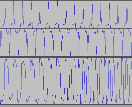
waveform
(source: toptensoftware.com)

The top signal is with the voltage divider, the bottom is the original line-level signal (probably saturating the iPhone's microphone preamp). As you can see it gets quite noisy around the centre. I believe the Microbee is basically looking for zero crossings when reading cassette - which would explain why it's not working.

I've tried putting various capacitors in parallel in an attempt to dampen the higher frequencies, but I don't really know what I'm doing and it made little difference.

I've also tried using a 10K pot for the voltage divider and found I could get semi-reliable recordings if I adjusted it up to just below clipping (according to the iPhone's level meter in the Voice Memos app), but for longer save files it always fails.

For reference, here's another related question including a circuit diagram and description of the Microbee's cassette interface.

Connecting an 80's style computer cassette to an FPGA

(Note that although that question is about connecting cassette to an FPGA, as far as this question is concerned I'm talking about a real Microbee)

So, my questions are:

  • what else could I try to get a less noisy, microphone level signal to the iPhone.
  • could this just be noise introduced by the iPhone's recording ability and/or encoding/compression? Seems unlikely.
  • would using a transformer as per this: http://www.blackcatsystems.com/ipad/iPad_iPhone_iPod_Touch_Microphone_Wiring.html be a better solution. eg: does a transformer give a different frequency response than that of a voltage divider (if I had the transformer I would have tried this already).

I'd really like to get this working reliably so any other ideas appreciated.

As a side note I've also tried using Pin 6 - Left Line-in on the iPhone/iPod dock connector however haven't been able to get the device to record (it play's through the dock connector, but won't recognize it for recording). I've tried with a 2nd Gen iPod Touch, a 5th Gen iPod Nano and an iPhone 3GS with no luck... but that's another question. I only mention it in case it's suggested as a solution


Just to clarify some points raised in the answers/comments:

  1. The higher frequency in the RHS of the bottom signal is perfectly normal. Microbee uses 2400Hz for 1 bits, 1200Hz for 0 bits. The two signals shown are representative only and were recorded at different times.

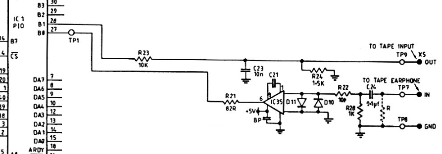
  2. In relation to where this signal was measured, from the Microbee's PIO pin 28, through the top half of the circuit shown below, then through the above described voltage divider, then into the iPhone where is was recorded. ie: the voltage divider would be across OUT/GND at the far right of the circuit below.


To save referencing the other question, here's the Microbee's cassette interface circuit:

MicrobeeSchematic

and a description of it:

The cassette data output consists merely of an RC network which accepts a signal from DB1, pin 28 of the PIO. The signal is attenuated and then decoupled prior to sending it to the cassette recorder MIC input. This signal appears on pin 3 of the 5 pin DIN socket.

The cassette data input circuit is slightly more complicated. The input from pin 5 of the DIN socket passes first to an attentuator -decoupler. Following this is a CA3140 op-amp, to allow a wide range of input levels to be squared up before the signal is passed to pin 27 of the PIO, DBO. The two diodes across the inverting and non-inverting inputs to the op-amp clip any input signals greater than the diodes' forward voltage in either direction. The 47pF capacitor is required by the CMOS op-amp for precompensation.

\$\endgroup\$
3
  • \$\begingroup\$ Hmmm...interesting project... What I see is a constant frequency on the top photo but the photo on buttom looks like a frequency modulation...are you sure your voltage divider works fine? I am a noob but that was my thoughts! \$\endgroup\$
    – Dumbo
    Commented Jul 26, 2012 at 8:05
  • 2
    \$\begingroup\$ @Sean87 - Yes the bottom trace is FSK (Frequency Shift Keying) what those computer cassettes used. I think the top trace is recorded at another time, with only the lower frequency visible. \$\endgroup\$
    – stevenvh
    Commented Jul 26, 2012 at 15:08
  • \$\begingroup\$ That's correct, ignore the right half of the bottom signal - it's the higher frequency of 1 bit. And yes these were recorded at different times. \$\endgroup\$ Commented Jul 27, 2012 at 2:02

3 Answers 3

3
+50
\$\begingroup\$

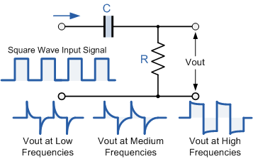
The top trace is a perfect output for a differentiated square-wave:

enter image description here

The \$C\$ is your coupling capacitor. This is a high-pass filter with

\$ f_c = \dfrac{1}{2 \pi RC}\$

So the higher RC the lower the cutoff frequency. If \$f_c\$ is lower than the signal frequency the signal will pass without much distortion, that's the rightmost waveform. As RC becomes lower the cutoff frequency will move to the right, and ultimately only the signal's highest frequency components will pass the filter. That's the leftmost waveform, only the edges will pass.

So to get a good reconstruction of your signal you'll have to increase RC. I'm not quite sure where exactly you measured this signal, so I don't know the components' values, but you may increase \$R\$ by a factor 10 to start with.

\$\endgroup\$
15
  • \$\begingroup\$ Oh those electronics-tutorials.ws images are just great \$\endgroup\$
    – m.Alin
    Commented Jul 26, 2012 at 15:07
  • \$\begingroup\$ @m.Alin - Sure they are! :-) Not just their images, BTW, though the site has a few errors here and there. \$\endgroup\$
    – stevenvh
    Commented Jul 26, 2012 at 15:09
  • \$\begingroup\$ I would not be at all surprised if the output of the computer has a capacitor in series with it; the input impedance of the voltage divider is too low for the capacitor, leading to the distorted waveform. If your series resistance is 10K, it would seem a bit surprising that the cap would be too small for that to work; it may be, however, that the computer's circuit design was counting on driving the input so far into saturation that it wouldn't matter what the wave shape was. \$\endgroup\$
    – supercat
    Commented Jul 26, 2012 at 17:21
  • \$\begingroup\$ BTW, I wonder why none of the popular 1980's computers tried to improve the performance and utility of cassette-based storage by reading and writing phase transitions directly (without bias), using a four-track head (using both stereo channels of both sides of the tape simultaneously), and using a faster motor speed when searching for or reading the tape header, than when reading and writing data. The Coleco Adam used some such techniques, but it couldn't use standard cassettes. \$\endgroup\$
    – supercat
    Commented Jul 26, 2012 at 17:26
  • \$\begingroup\$ @supercat - I think the last 6 words may be the explanation. Compact cassettes and their recorders were cheap, a new format would have been more expensive because of the new developments that would be required. Remember that some of those hobby computers were sold at 150 dollar at the time. \$\endgroup\$
    – stevenvh
    Commented Jul 26, 2012 at 17:32
1
\$\begingroup\$

It appears that the voltage divider network is not working as it should. This is most likely due to either a very high output impedance of the microbe is really high (it can't push enough current to maintain a stable voltage) or there is a very high inductance somewhere in your circuit.

The first thing I would try is some higher values resistors. instead of a 10k potentiometer, try a 1M potentiometer. Don't use any values smaller than 100k if you are using discrete resistors.

If this is something you are going to be doing frequently, you should use two opamps to step down the voltage. Grab a tl072 from radioshack, find a 5 or 10v wall wart, supply the power to the rails of the op amp, use resistors to make an inverting op amp configuration connect the first op amp to the second op amp that is also in an inverting configuration. set the gain on both op amps to reduce the output. Use high-ish value transistors (10k to 500k) remember that the gain equations multiply.

Hope this helps.

\$\endgroup\$
2
  • 3
    \$\begingroup\$ Not RadioShack. They don't know an analog comparator from a shift register. \$\endgroup\$
    – stevenvh
    Commented Jul 26, 2012 at 14:36
  • \$\begingroup\$ I typically use the 'go away I will find the part I am looking for on my own' approach at radio-shack :/ I'm not saying I am a fan, but they are convenient. \$\endgroup\$ Commented Jul 26, 2012 at 23:07
1
\$\begingroup\$

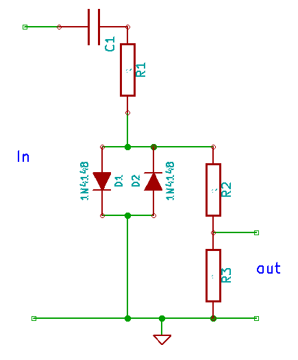
This is my idea in one of the comments elsewhere. The idea is to use the clipping characteristic of the diodes to shape the input signal to nice clean pulses. R1, D1 and D2 form a pulse shaper at +/- 600mV. Regardless the input voltage, the voltage at the diodes will not rise above +/- 600mV.

C1 removes the DC component in the signal.

The voltage divider at the right then changes the voltage to the required input voltage of the recording device. From the other question I understood iPhone input level is about 6mV, so the 600mV at the diodes is reduced by a factor 100 using R2 and R3.

Diodes in my opinion can be 1N4148, but the resistors and the capacitors are entirely up to the applied voltages. I think an input impedance of 10 - 50kΩ should be just fine, and output impedance should be relatively low. Guessing output voltage at approx 6mV then:

  • C = 100nF
  • R1 = 22kΩ
  • D1 = D2 = 1N4148
  • R2 = 47kΩ
  • R3 = 470Ω

pulseShaper

\$\endgroup\$
3
  • \$\begingroup\$ That looks remarkably similar to the input circuit used by the Microbee when reading cassettes back in (see link in question). I don't really understand how these two diodes work in that arrangement though. Is there a name for that type of circuit that I can read up on? \$\endgroup\$ Commented Jul 27, 2012 at 3:59
  • \$\begingroup\$ Mind you the values for the various components are guesstimates as exact in- and output specifications are unknown to me. I don't expect them to be very far off though. \$\endgroup\$
    – jippie
    Commented Jul 27, 2012 at 6:21
  • \$\begingroup\$ @Brad - The diodes clip the signal to + and - 0.7 V. The resistor divider R2/R3 will scale this down to lower limits. \$\endgroup\$
    – stevenvh
    Commented Jul 27, 2012 at 6:22

Your Answer

By clicking “Post Your Answer”, you agree to our terms of service and acknowledge you have read our privacy policy.

Not the answer you're looking for? Browse other questions tagged or ask your own question.