7
\$\begingroup\$

I have a PCI 5V GPIO card which bit-bangs SPI over a 10-foot cable. The SPI clock is running at 800Khz. The cable connects to a board and the SPI lines feed directly into the SPI IC's. I know SPI is a short, board level communication, but I can't change any of that going forward.

When I looked at the SPI clock and MOSI lines, I was seeing a 12V pulse on rising/falling edge that lasted for about 40ns. That tells me there is significant transmission line inductance. I can't change anything on the PCI card/cable and I am not able to slow down the drive strength of the line. I tried adding 100 ohms series resistance on the board side, but that had no effect since the inductance is still between the drive and the series resistor. An RC filter on the board side of 100 ohms, 1nF also had little effect.

My next step, is to add an IC buffer that can handle the spikes and not pass them through. I just wanted to see if anyone else had a suggestion or could recommend a good IC buffer.

Thanks.

\$\endgroup\$
14
  • \$\begingroup\$ Do you have a specific issue with the spikes? \$\endgroup\$
    – clabacchio
    Commented Jul 25, 2012 at 14:34
  • 1
    \$\begingroup\$ @clabacchio - I should think so. 12 V on a 5 V supply is 140 % overshoot. \$\endgroup\$
    – stevenvh
    Commented Jul 25, 2012 at 14:50
  • 3
    \$\begingroup\$ Something is fishy here. If you just had a transmission line mismatch, you could not have more than 100% overshoot. It would be good to understand the root cause of the problem before trying to suggest an answer. Could you post a photo of the system to make clear the construction of the boards, cables, etc.? A scope trace of the overshoot signal? \$\endgroup\$
    – The Photon
    Commented Jul 25, 2012 at 16:15
  • 2
    \$\begingroup\$ Is the cable ribbon cable? coax? twisted-pair? What are the wire sizes? Does it have equal number of signal and ground wires? What's the arrangement of signal relative to ground wires? When you observed the 12 V overshoot, how and where were you probing your circuit? What was the duration of the overshoot? Was there equal undershoot on falling edges? Can you post a schematic of your receiving circuit? \$\endgroup\$
    – The Photon
    Commented Jul 25, 2012 at 16:19
  • 1
    \$\begingroup\$ You could add resistor and two schottkys at the receiver. The schottky will clip the voltage at Vcc+Vf - where Vf is the forward voltage drop of the diode. \$\endgroup\$
    – Saad
    Commented Jul 25, 2012 at 16:47

3 Answers 3

4
\$\begingroup\$

You are misapplying the resistor.

The problem is that the input of the receiving chip has a higher impedance than the characteristic impedance of the transmission line. Putting in a series resistor at the destination won't help much with the initial problem. Instead, you should use a shunt resistor to ground.

If you want to use a series resistor, it needs to be at the sending end. Because the driver has a low impedance relative to the transmission line, you get a discontinuity there too, and an inverted reflection results. If you put a series resistor at the driver matching the line impedance, then that is absorbed, and you eliminate the ringing caused by back-and-forth propagation of inverted reflections which is so evident on your scope.

An interesting case is a series resistor at the driver, and a high impedance receiver input without a terminator. Initially, the series resistor and line impedance form a voltage divider, and only half the applied step goes down the line. When it gets to the "open" end formed by the receiver, it reflects in phase, doubling the voltage back to the original. When the reflection gets back to the transmitter, it is absorbed by the receiver. Gradually the line voltage floats up to the drive voltage, as the situations becomes more like DC than like a step function.

\$\endgroup\$
2
\$\begingroup\$

Right now I have a 'good enough' solution, but I'd like get a better idea on this going forward.

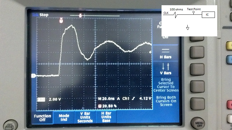
Pic 1 is of 100 ohms in series on the PWB side. As you can see the spike on the 5V clock signal dropped from 12V to 9V, but is still way too high. Larger series resistance such as 200 ohms had little further effect. Pic 1 - 100 ohms in series

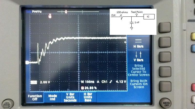
Pic 2 is of 100 ohms/1nf filter on the PWB side. I miss spoke when I said there was no difference. The spike drops in voltage but is still there right at the beginning. This is not a workable solution because my clock is unusable now. Pic 2 - 100 ohm / 1nF cap

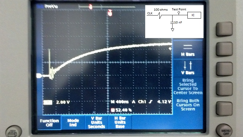
Pic 3 is of the 100 ohm/10 nf filter on the PWB side. The spike is still there and has not dropped in value. Pic 3 - 100 ohm / 10nF cap

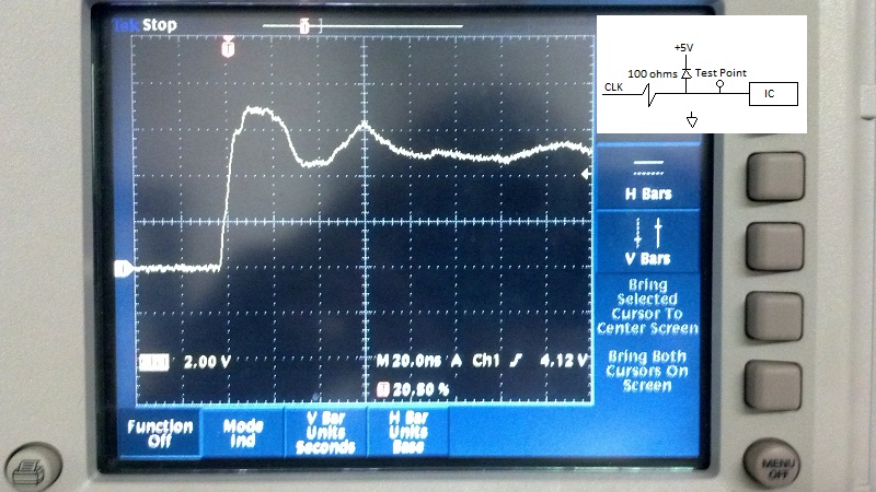
Pic 4 is of the 'good enough' solution. I've added a diode to the 5V rail to dissipate the spike into the rail. (At the moment, I'm using a 1N4001 which is really slow, but it's all I had on hand. I plan on swapping that out with a 1N4148 which is much faster as soon as I get some.) As you can see, the spike is 7V and the undershoot only drops to 4V which is well above the 3.5V minimum high signal. Again, this will get me there, but if anyone has any other comments, I'd love to read them. enter image description here

Thanks to everyone for their comments and thoughts.

\$\endgroup\$
2
  • \$\begingroup\$ The 1n4148 may or may not be fast enough but sure as heck will drop quite a bit of volage. It's forward voltage is significantly higher than a Schottky diode (0.2 V to 0.5 V). I think a Schottky would be preferable here. \$\endgroup\$
    – Saad
    Commented Jul 27, 2012 at 20:17
  • 1
    \$\begingroup\$ See this question: electronics.stackexchange.com/questions/35807/… for discussion between me and StevenVH on when a Schottky to Vcc is a good solution, and when you might need something different (Zener). \$\endgroup\$
    – The Photon
    Commented Jul 27, 2012 at 20:29
0
\$\begingroup\$

I can't even give a hint on your actual problem, but I think my comment is worth to have the status of an answer.

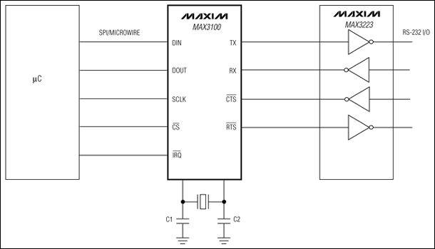
What about SPI/UART converter? Easy to interface, can be done on a minimal breadboard. 8 bucks.

enter image description here

Sure, this will cost you around 20$, but if you replace RS-232 with 485 transceiver, you can forget about any problems related to cable length.

\$\endgroup\$
2
  • \$\begingroup\$ 20 dollar is expensive for a 3 m long connection. And as long as we don't know the cause of the problem we can't be sure that this is a solution. \$\endgroup\$
    – stevenvh
    Commented Jul 25, 2012 at 14:54
  • \$\begingroup\$ Unfortunately I can't change anything on the PC/cable/software side so that all has to remain SPI. I agree that using a standard that is meant for distance - 232/485/LVDS is the best way to design, but that's not an option at this point. Let's remove the communication for a moment and just look at a single GPIO line. Since the spike is occurring on the level transition, even if I switched a line once I would still get that huge spike, which is an issue because it could damage the electronics. I appreciate the suggestion though. Thanks. \$\endgroup\$
    – Peter
    Commented Jul 25, 2012 at 15:23

Your Answer

By clicking “Post Your Answer”, you agree to our terms of service and acknowledge you have read our privacy policy.

Not the answer you're looking for? Browse other questions tagged or ask your own question.