15
\$\begingroup\$

I'm designing a step-up constant current source to drive LED strips (nominal load voltage is about 54 VDC). Requirements:

  • Vin: 18..32 VDC
  • Iout = 0.2 A
  • Vout = 54 VDC (nominal) - 57 VDC (maximum)

Since the circuit should have an on-off input, I decided to use LM2586SX-ADJ.


Problem

A hand-made fast prototype worked fine at the R&D stage, so we manufactured a hundred of the circuit. The circuit works fine after energizing. However, after some time (I really can't say an exact duration, but it varies between 15 minutes and 1 hour) the inductor starts to buzz, overheats and then finally fails permanently (burns) in a few seconds. I've to say that both the IC and the inductor keep quite cool during normal operation.


What I've tried

  • At first, I thought that the problem comes from the DC resistance of the inductor. So I replaced the inductor with 7447709681 from Würth. It didn't help.
  • Increased the switching frequency to nearly 200 kHz. It didn't help.
  • Placed a 0.1 µ capacitor across the input of the LM2586. It didn't help.
  • Placed a snubber (47 Ω and 10 nF) across the SW pin. It didn't help.

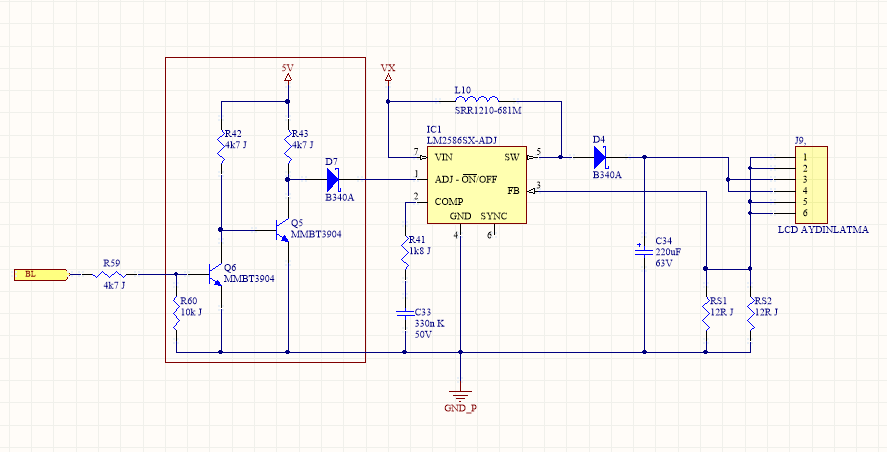
Schematic:

Enter image description here

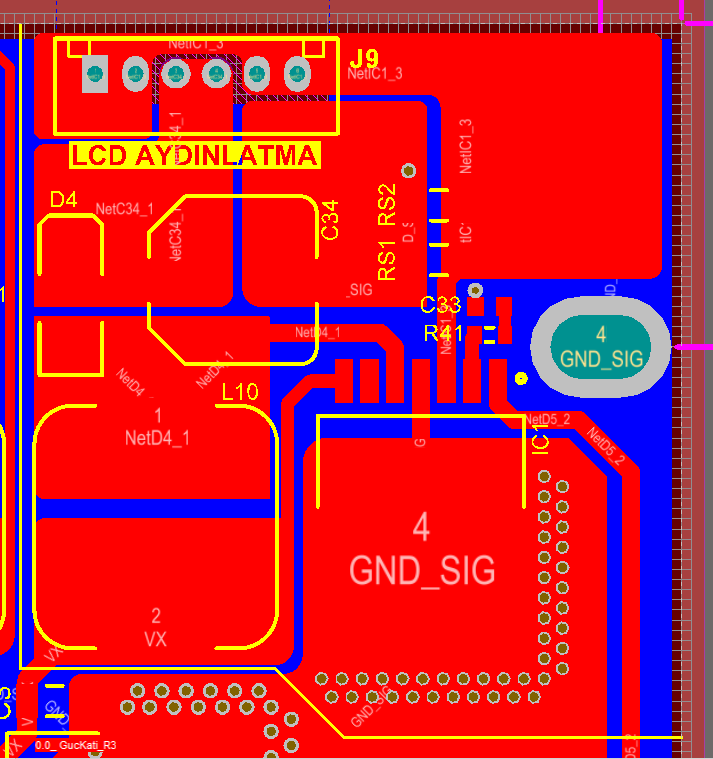
PCB:

Enter image description here


NOTES:

  • The bottom layer is completely GND with neither cuts nor holes.
  • There's a pi filter (100 µF elco - 68 µH - 100 µF elco) before the input, VX. But it's in another sheet, so I couldn't show it here.
  • BL input comes from the microcontroller (5 V or GND).

So I'm stuck at this problem. Any help will be greatly appreciated.

\$\endgroup\$
12
  • 3
    \$\begingroup\$ Not much voltage margin on C34, the output cap, when operating at 57V out. Have you put a scope on a working board and measured the peak output voltage at that point? \$\endgroup\$
    – AlmostDone
    Commented Mar 29, 2018 at 15:08
  • 3
    \$\begingroup\$ How is that feedback supposed to work? \$\endgroup\$
    – Oldfart
    Commented Mar 29, 2018 at 15:15
  • 1
    \$\begingroup\$ @RohatKılıç, the way the feedback pin node works is it varies the SW node until the input pin sees the voltage it expects (1.23VDC). The pin itself is high impedance and will neither source or sink current. (Or maybe I'm out to lunch). Requires resistor divider across C34 to FB pin. \$\endgroup\$ Commented Mar 29, 2018 at 15:50
  • 2
    \$\begingroup\$ @Brian no it doesn't. Those resistors are placed on the return path of the load so that the load current flows through them. Since the voltage across these resistors will be kept at 1.23VDC, the output current will be kept at 205mA even if the load voltage varies. Just look from a different perspective: Constant output voltage & load-dependent output current vs Constant output current & load-dependent output voltage. \$\endgroup\$ Commented Mar 29, 2018 at 15:52
  • 2
    \$\begingroup\$ You might not deliberately disconnect the load but it looks like it goes through a connector so it can happen. Or the load could fail and go open circuit. Either way, the regulator will go flat out trying to make the FB pin voltage high enough. With nothing to stop it, it could exceed the rated voltages of capacitor, diode or IC. I'd add something to stop that happening. \$\endgroup\$
    – Finbarr
    Commented Mar 29, 2018 at 22:09

3 Answers 3

13
\$\begingroup\$

I believe you are exceeding the peak inverse voltage (PRV) rating of D4, the 40 V Schottky diode. During your switching cycle when the SW pin on the 2586 goes to 0 V, D4 becomes reverse biased due to the level at the output at the top of C34. With the output set to 57 V, this exceeds the 40 V reverse rating of D4. This can only be observed and measured with an oscilloscope; you cannot see this with a multimeter.

Whether this is the cause or there's still something else, I suggest you use a 60 V diode in place of the 40 V for D4.

More detailed explanation:

When the switch is off, charge is pumped into C34 and is drained off by the load. With the diode shorted, C34 no longer holds that charge when the switch is on, but quickly decreases toward zero. The feedback senses the drop and the switching controller commands a longer on time to build up a higher current in the inductor. When this on time becomes long enough, the inductor will saturate. When saturated, it no longer functions as an inductor, and the current through L10 will be limited by only its winding resistance and applied voltage.

\$\endgroup\$
3
  • 6
    \$\begingroup\$ A 60 V diode for 57 V DC out max? Better use one with 70 V. \$\endgroup\$
    – Uwe
    Commented Mar 29, 2018 at 16:52
  • \$\begingroup\$ Okay but, dont misunderdtand, I couldnt understand how this results in burning the power inductor. Could you please elaborate? \$\endgroup\$ Commented Mar 29, 2018 at 17:19
  • 6
    \$\begingroup\$ When the switch is off, charge is pumped into C34 and is drained off by the load. With the diode shorted, C34 no longer holds that charge when the switch is on, but quickly decreases toward zero. The feedback senses the drop and the switching controller commands a longer on time to build up a higher current in the inductor. When this on time becomes long enough, the inductor will saturate. When saturated, it no longer functions as an inductor, and the current through L10 will be limited by only its winding resistance and applied voltage. \$\endgroup\$
    – AlmostDone
    Commented Mar 29, 2018 at 19:44
19
\$\begingroup\$

I'd suggest your B340A diode is avalanching since you are far exceeding its reverse voltage rating.

Enter image description here

The diode must standoff the voltage you generate, so you need a voltage rating above your capacitor voltage. I'd use something in the 75-100 volt range, and perhaps an ES07B would suffice.

\$\endgroup\$
3
  • 4
    \$\begingroup\$ Ding ding ding! Smoking gun right here. \$\endgroup\$
    – winny
    Commented Mar 29, 2018 at 16:30
  • 4
    \$\begingroup\$ @RohatKılıç Long story short (and simplified): your diode short circuits because it can't handle the voltage. Get one with a higher maximum peak reverse voltage, try double. \$\endgroup\$
    – Mast
    Commented Mar 29, 2018 at 22:26
  • 1
    \$\begingroup\$ Alright, I see now. I have ES1G (400V/1A) at hand and I'll replace the diode with this. I hope this will solve because it cost me about 2 weeks. \$\endgroup\$ Commented Mar 30, 2018 at 5:02
3
\$\begingroup\$

D4 should have a voltage rating 3 times the expected DC output just for a 50% safety margin. The reason is that when C4 has 57 volts on it the diode sees both the 57 volts and the zero volts when the internal MOSFET is ON again. Now it has 57 volts on it in reverse. Then another surge of forward current.

The inductor is overheating due to D4 shorting out, so the inductor and the MOSFET get the capacitor charge fed back to them.

Insert a fast diode with at least a 200 volt rating and this problem will go away.

\$\endgroup\$

Your Answer

By clicking “Post Your Answer”, you agree to our terms of service and acknowledge you have read our privacy policy.

Not the answer you're looking for? Browse other questions tagged or ask your own question.