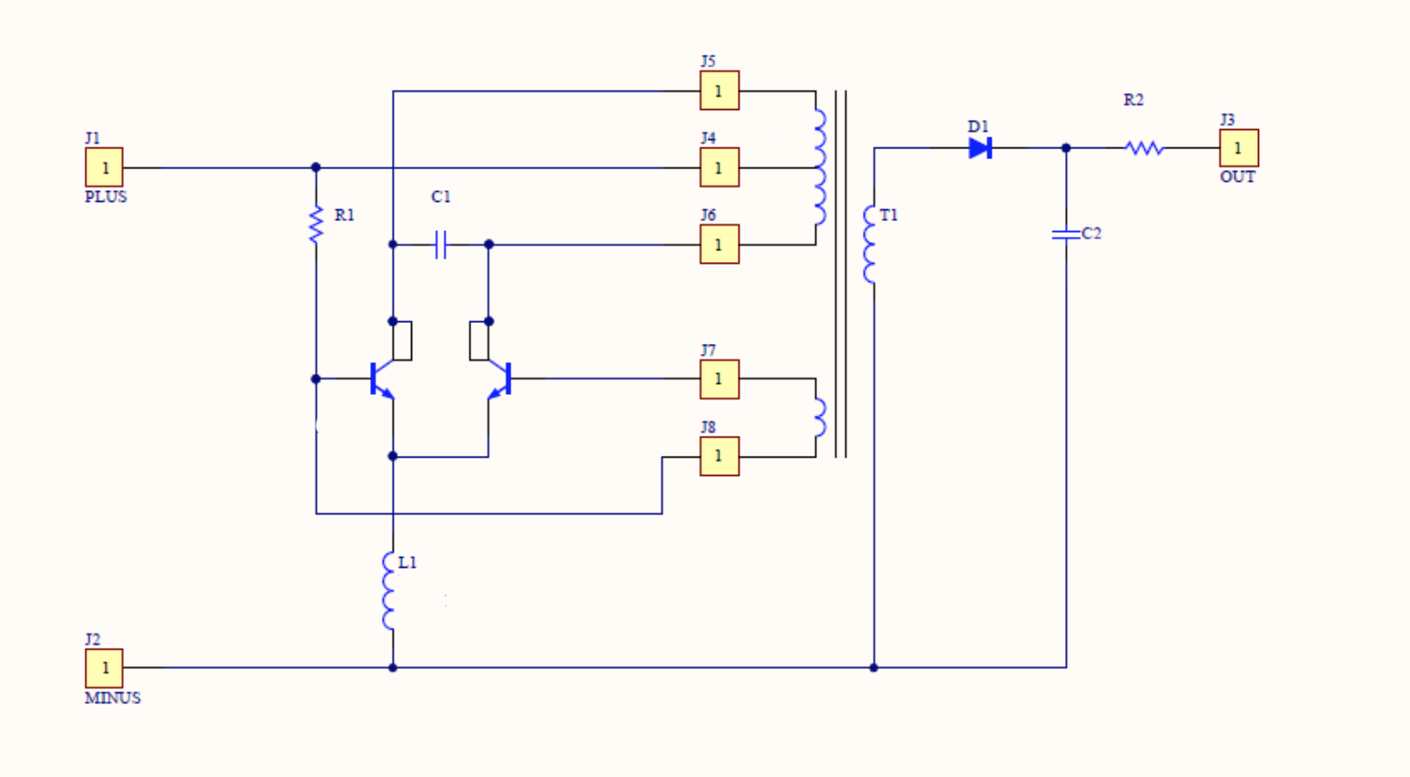
every one, I am an automation engineer, not an electrical, but I have some knowledge about electricity (I hope). I am designing a power supply with input voltage of 3,1V and the output voltage of 175V (10mA max). I am using push-pull configuration like on the figure below.
This schematic requires custom transformer. I am pretty much limited with free space within enclosure. As a “real” engineer to make this power supply I first tried to brute force the problem. After few failed attempts I have a working prototype on the breadboard. I winded the transformer from an inductor. It functions approximately at 230 kHz (I know, 230 kHz and breadboard is complete nonsense and stupid). That is why probably I have so much lose and terrible energy conversion efficiency, as well as because the transistors are getting very hot(I believe they are running at their maximum).
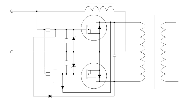
In order to make everything properly this time I read a book “TRANSFORMER AND INDUCTOR DESIGN HANDBOOK Third Edition, Revised and Expanded “ by COLONEL WM. T. MCLYMAN. Link to the book Link to the book . If I understand correctly in order to decrease the size I should to increase frequency even more. So I decided to switch to MOSFETs. The schematics with MOSFETs looks as follows.
I have Si7940DP laying around, so I will using it. Also in order to increase energy conversion efficiency I want to wind a proper transformer. I have made calculations (version in google sheets with formulas) for that. Calculations have been made according to the chapter 7 from the book.
Can somebody verify my calculations and say to we that I am not dreaming or vice versa. That I can reach such frequency with MOSFETs and transformer Also there are few sings that I do not understand completely, they are marked with red. There are: 1. How to choose “Operating flux density” and how it affects the design? 2. And how to choose “Magnetic material”, what Permeability (L - 900, R - 2300) suits better?
Hate and critics are welcome. Let me know if additional information required.
Thanks for help, Arttu


