0
\$\begingroup\$

I draw a new schematic, which uses a operational amplifier to turn on a n-channel mosfet when the night comes.

I used a article from internet to make the connections of the unused operational amplifier. I tested today the schematic and it works. The power supply is an 12V, LM317 power supply, but I am planning to use a 12V 2A SMPS for this project. The LED_load connector is for connecting a few leds with series resistor. The total power consumption of the leds will be about 100-200mA.

This is the schematic: View post on imgur.com enter image description here
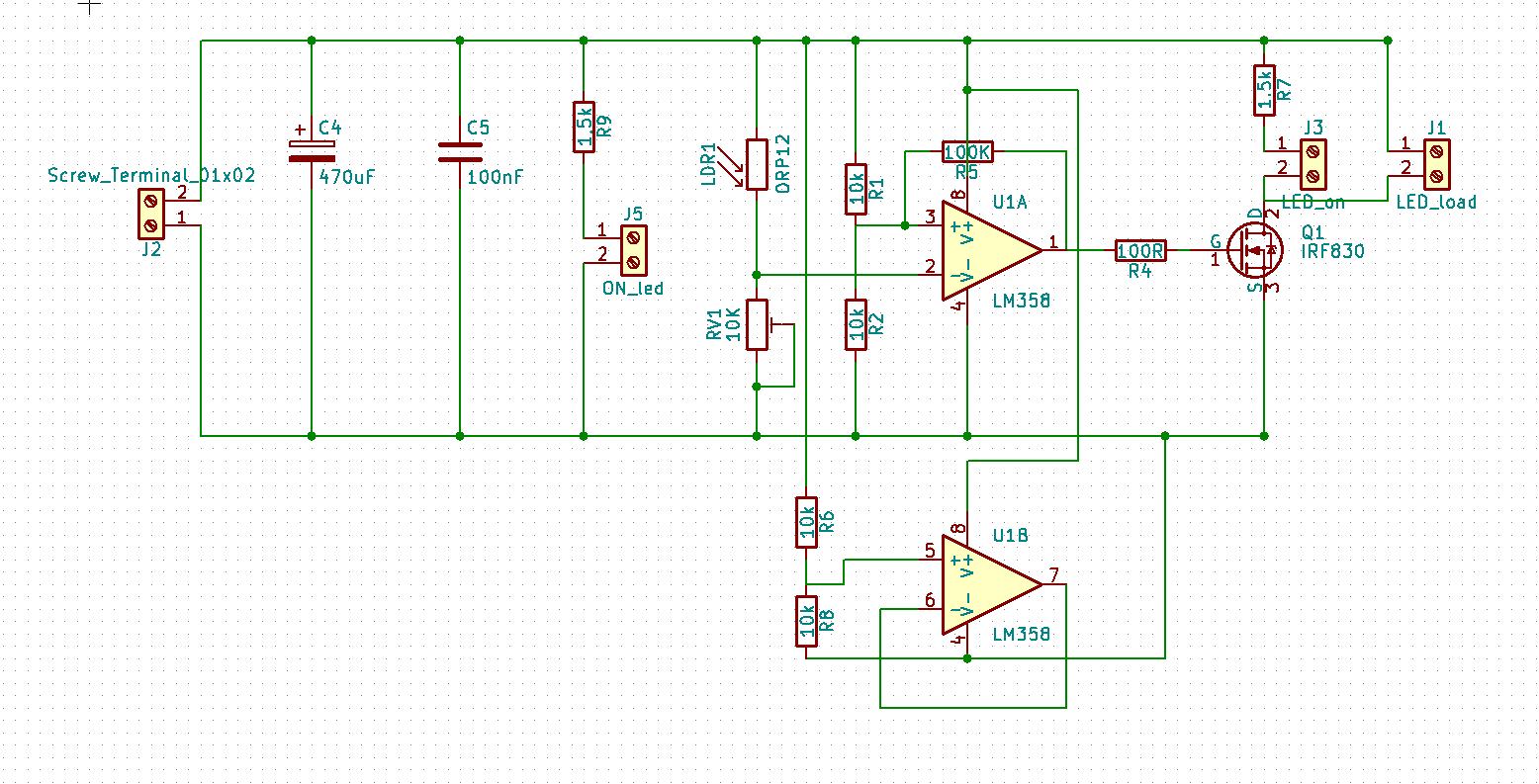
Please have a look at the schematic and tell me what you think. I am interested especially if the connection between the operational amplifier and mosfet is good.

Is the schematic correct ?

\$\endgroup\$
2
  • \$\begingroup\$ R5 is much too small. Try 10k - 100k instead, with 100k as your starting point. \$\endgroup\$ Commented Apr 21, 2018 at 21:26
  • \$\begingroup\$ Make sure the LDR does not get light from the LEDs otherwise it won’t look like night. Increase R5 towards 1M \$\endgroup\$
    – D.A.S.
    Commented Apr 21, 2018 at 22:53

1 Answer 1

1
\$\begingroup\$

Looks okay to me.

I do wonder about the interaction of your LED and the LDR, which may cause the LED to blink despite your moderate amount of hysteresis.

You may also wish to bypass the 10K pot with 100n. I presume you've tested the LDR response and 5K-ish is about the resistance at the switching point, if not you should do that test.

\$\endgroup\$
9
  • \$\begingroup\$ Thanks for the reply @Spehro Pefhany . The connection of the unused operational amplifier is also correct ? \$\endgroup\$
    – beard999
    Commented Apr 22, 2018 at 18:48
  • \$\begingroup\$ It's perhaps a bit overly conservative in this case, but this method is 'best practice' for a unity-gain stable op-amp. You could tie the non-inverting input to pin 3 or 2 of the other op-amp and save a couple resistors at the expense of slightly more bias current. \$\endgroup\$ Commented Apr 22, 2018 at 19:06
  • \$\begingroup\$ Thanks for the reply @Spehro Pefhany The connection between the operational amplifier and mosfet is correct ? The 100 ohm resistor is enought ? \$\endgroup\$
    – beard999
    Commented Apr 26, 2018 at 5:39
  • \$\begingroup\$ Regarding the 100 ohm resistor, it has a sufficient value to limit the inrush current of the mosfets gate or it should have a bigger value ? @Spehro Pefhany \$\endgroup\$
    – beard999
    Commented Apr 26, 2018 at 10:50
  • \$\begingroup\$ It will work fine. If you increase it to 1K or 3K it will make the hysteresis a bit snappier because it won't load the op-amp output as much. The only disadvantage to a high value is that it slows the MOSFET so it will result in more switching loss (but unless you get feedback between LED and LDR you should not be switching frequently). If you had an SOT-23 power MOSFET it would be more of a concern. \$\endgroup\$ Commented Apr 26, 2018 at 12:51

Your Answer

By clicking “Post Your Answer”, you agree to our terms of service and acknowledge you have read our privacy policy.

Not the answer you're looking for? Browse other questions tagged or ask your own question.