1
\$\begingroup\$

I'm trying to build a circuit around an existing switch that allows another component to override the switch state. (Our component is a computer and the feature we're trying to build is remote-activation).

I want the "ON/OFF" state to reflect the last thing to toggle the state. (i.e. If the switch is "on", our component can logically turn it off. If the switch is toggled off, nothing happens, then if the switch is toggled back on it turns on).

I control both sides of the switch and I have two "short to ground" switches (controlled by our component).

I don't want to depend on either of the two switches being held closed for ON mode (i.e. The short to ground switches should work like push button switches). This is so that software failures/resets on our component won't accidentally set the mode to OFF.

I'm pretty sure I can do this with some mosfet latching circuits but I'm quite novice at electronic design. Any suggestions are appreciated!

Edit: here's some more clarifying info:

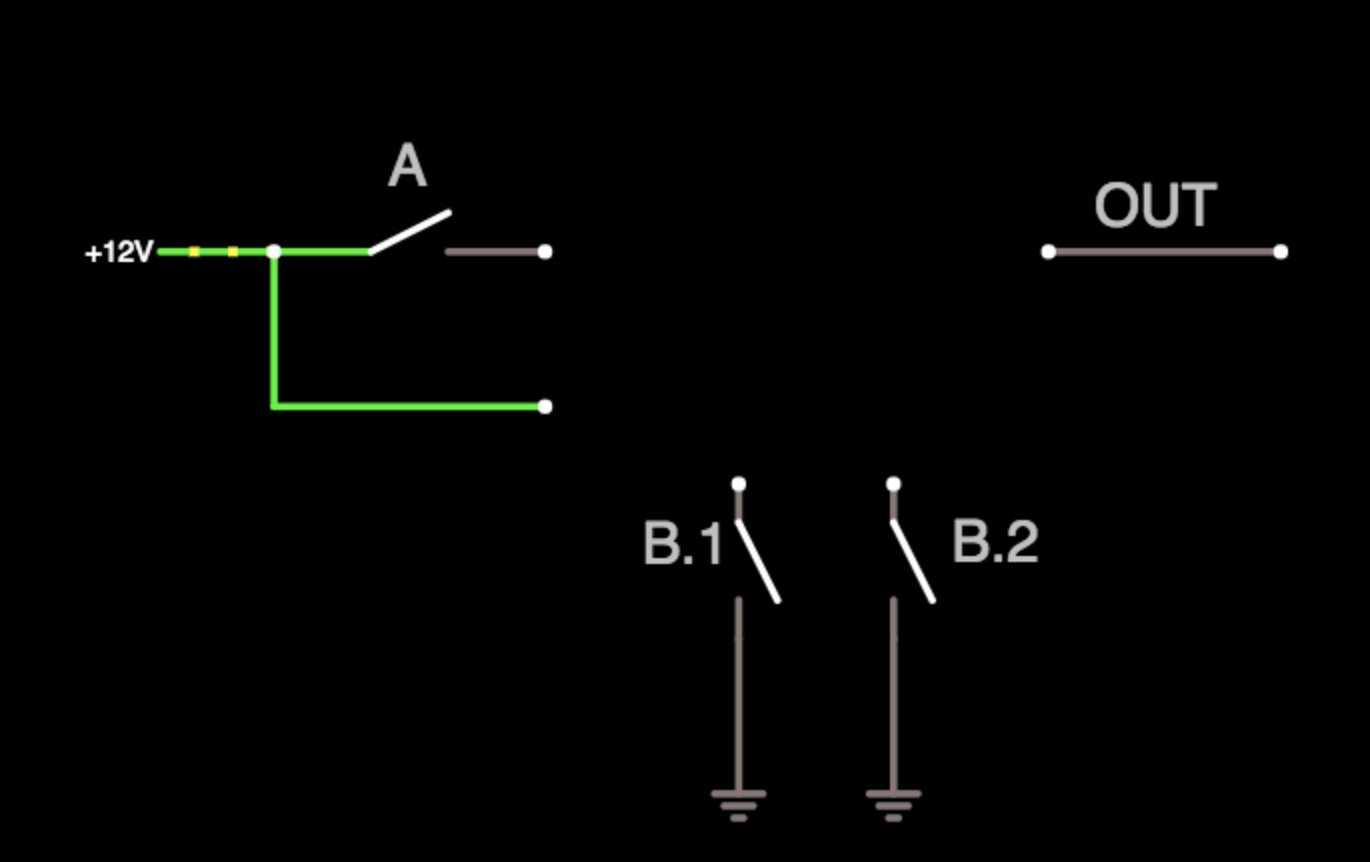
Circuit inputs/outputs

Here's a state diagram of what I want. Both B.1 and B.2 should only even be pulsed closed, so they can't be counted on to be held closed to achieve a desired state. Notably, the desired behavior is edge-triggered by the switch state.

enter image description here

\$\endgroup\$
8
  • 1
    \$\begingroup\$ I think a state diagram is in order. I'm just not able to read your writing well enough to feel as though I completely understand the situation. \$\endgroup\$
    – jonk
    Commented May 1, 2018 at 22:34
  • \$\begingroup\$ Thanks for the suggestion. I added some clarifying remarks and a blank circuit diagram. \$\endgroup\$
    – jdizzle
    Commented May 2, 2018 at 3:39
  • \$\begingroup\$ Odd. So A is an SPST switch, not momentary? \$\endgroup\$
    – jonk
    Commented May 2, 2018 at 3:45
  • \$\begingroup\$ Correct, it's an actual toggle switch. It's part of the existing electronics I need to interact with. \$\endgroup\$
    – jdizzle
    Commented May 2, 2018 at 4:28
  • \$\begingroup\$ You really need a state diagram. Not words providing haphazard examples. It looks now to me like you have two "B" signals: one to remote-activate and one to remote-deactivate. But I could just consider it a single signal, which has a rising edge (activate) and falling edge (de-activate.) Or perhaps you really do need two signals. I can't be sure. This might be your state diagram, for example. Green arrows are "remote activate;" red arrows are "remote deactivate;" and "A" means the physical A-switch changes state. \$\endgroup\$
    – jonk
    Commented May 2, 2018 at 5:05

2 Answers 2

1
\$\begingroup\$

schematic

simulate this circuit – Schematic created using CircuitLab

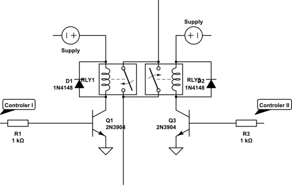
If I understand you right then you want the circuit to come ON if either of sources want it to be on. SO for basics I would use relays in paralel with its relevant transistor and diodes as protection. Signal from controler is connected to the base with suitable resistor (for arduinos mine favourite is usually 1K) The relays have solenoids + connected to the supply and ground to collector. Emitor is grounded. the diode goes in OPOSITE direction between relays winding to protect the transistor when it switches off

will be in parallel and As on "OR" System: if either is final circuit is on. each can only switch its own relay so can only switch its own relay off. All three circuits are fully isolated.

\$\endgroup\$
3
  • 1
    \$\begingroup\$ Thanks for your reply! I believe I understand this as a simple "or" circuit, but I want some edition edge triggered behavior: Always turn device off when switch is flipped to off position, even if the other controller does latched it on. \$\endgroup\$
    – jdizzle
    Commented May 2, 2018 at 1:55
  • \$\begingroup\$ I added some more exposition to the original question. \$\endgroup\$
    – jdizzle
    Commented May 2, 2018 at 3:41
  • \$\begingroup\$ @jdizzle already got your answer? \$\endgroup\$
    – Unknown123
    Commented Jun 5, 2019 at 21:44
1
\$\begingroup\$

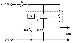
A dual - coil latch relay 'K' is all that is required.

Here's the schematic.

enter image description here

Pulsing B.1 and B.2 sets and resets the relay respectively.

\$\endgroup\$

Your Answer

By clicking “Post Your Answer”, you agree to our terms of service and acknowledge you have read our privacy policy.

Not the answer you're looking for? Browse other questions tagged or ask your own question.