0
\$\begingroup\$

Sorry if this has been asked before; I'm still learning about electronics and probably don't have the right vocabulary to describe this part's functionality.

I came across an interesting part made by NXP when looking for simple ways to get a constant current source of around 20mA for trickle-charging some nickel batteries. The part is the 'PSSI2021SAY', from NXP:

https://assets.nexperia.com/documents/data-sheet/PSSI2021SAY.pdf

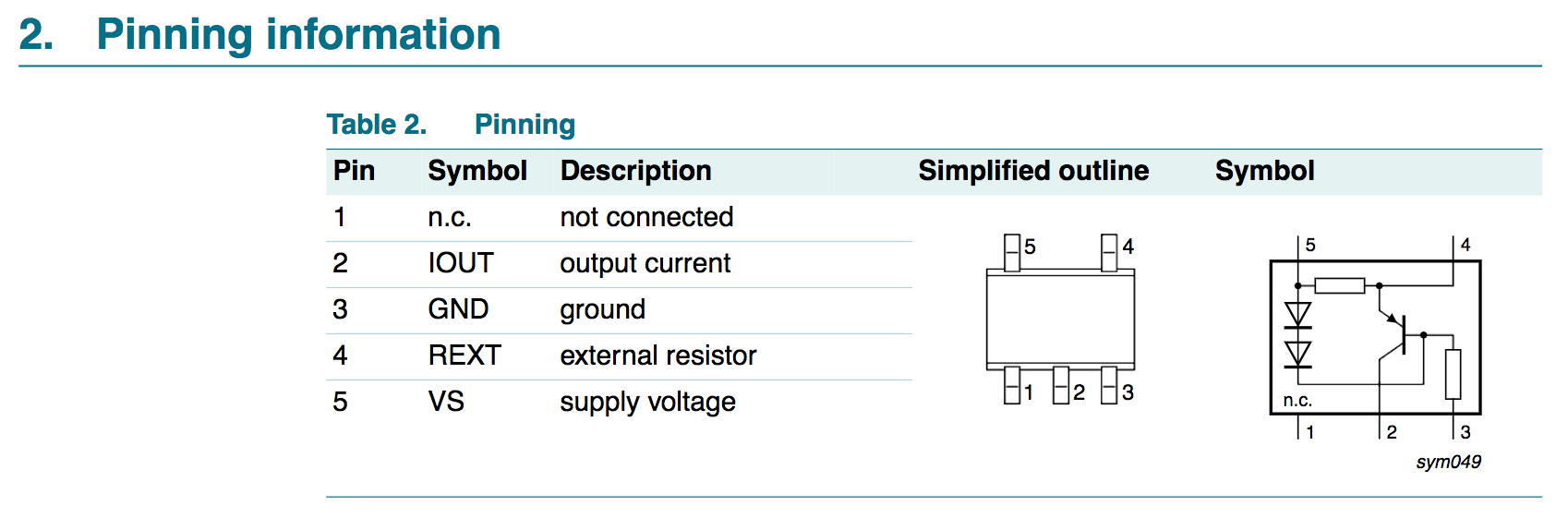
It is currently out of stock on Digikey, but glancing at the datasheet, it looks like it should be simple to make a similar circuit out of a PNP transistor, a couple of diodes, and a few resistors:

Block diagram and pinout

My questions are, how does this topology work? Does it require a stable input voltage or other external factors? Does the transistor need any special properties? What about the diodes/resistors?

It looks like it is somewhat cheaper than most other parts with a similar function, so in a nutshell, what's the catch?

\$\endgroup\$
5
  • 1
    \$\begingroup\$ Google "current mirror". If you want to build a discrete version you need matched transistors or lots of emitter resistance. (You don't use diodes, but transistors with the base and collector connected together.) \$\endgroup\$
    – John D
    Commented May 2, 2018 at 21:19
  • 1
    \$\begingroup\$ @JohnD With 0.7V-ish margin and an aproximate requirement of 20mA, you don't need matching at all. Two 1N4148's or similar is just fine, since the emitter resistance will inherently be big enough compared to current range, and for LEDs or trickle-charging +/-20% on the current is unlikely to be an issue. \$\endgroup\$
    – Asmyldof
    Commented May 2, 2018 at 21:28
  • 1
    \$\begingroup\$ @Asmyldof Good points, no argument. I was in a hurry so left the comment too quickly. \$\endgroup\$
    – John D
    Commented May 2, 2018 at 21:51
  • 1
    \$\begingroup\$ ON Semi have a range of CC 2 terminal devices that are very economic: onsemi.com/pub/Collateral/NSI45020A-D.PDF Much easier to use and take almost zero PCB footprint. \$\endgroup\$ Commented May 2, 2018 at 22:08
  • 1
    \$\begingroup\$ The following current matching discussion might be a little bit useful. But the basic idea is that one of the diodes in series compensates for the VBE drop on the transistor, leaving the remaining diode to present a matching diode drop across the internal resistor (which you can adjust externally.) That drop across the resistance achieves a "constant" current of sorts at the collector. \$\endgroup\$
    – jonk
    Commented May 2, 2018 at 22:47

1 Answer 1

1
\$\begingroup\$

Here is an equivalent circuit with parts values. Any general purpose transistors can be used. You cannot substitute diodes for the diode-connected transistors and have it behave quite the same way, because of the ideality factor in the Shockley equation. With diodes the current will be lower than typical for the IC with the stated 48K internal resistor. You could also use something like an LED rather than the transistors or diodes.

Basically the voltage across the two diodes Q2/Q3 is relatively constant with current and is (ignoring the current difference) about one diode drop more than the Vbe drop of Q1 so that voltage appears across R1 (in parallel with an external resistor if desired) and so you get a collector current of about 0.7V/(R1 || Rext).

schematic

simulate this circuit – Schematic created using CircuitLab

The catch? It's not a very constant current source. It's temperature sensitive (-0.15%/°C, including self-heating) and has relatively poor line regulation (changing the supply voltage from 12V to 24V changes the output current by about 6%.

A discrete version could be made a bit more stable from self-heating by coupling,say Q2 thermally to Q1 and allowing Q3 to be independent, but it's hardly worth it.

\$\endgroup\$
1
  • \$\begingroup\$ So it sounds like this sort of circuit is much better than a resistor to limit current across a wide voltage range, but shouldn't be used for precise current references. But it seems like it can probably be suitable for something like targeting a ~0.05C charge rate on a small battery from a variable voltage source. Thank you! \$\endgroup\$
    – Will
    Commented May 3, 2018 at 16:22

Your Answer

By clicking “Post Your Answer”, you agree to our terms of service and acknowledge you have read our privacy policy.

Not the answer you're looking for? Browse other questions tagged or ask your own question.