Some background: I am a mechatronics engineer and I have just recently started my first job out of university as an electrical engineer. I feel a little out of my depth but I wasn't going to turn the job down. My first project at work requires me to design a system to wirelessly transmit encoder data to drive a slave conveyor table.
I'm required to use IR light to transmit the data over fairly small distances (<1m, probably 20cm or so). Using IR light is a hard requirement set by my boss.
I am currently using the following systems:
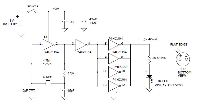
For transmission, I am using what I believe is a Pierce crystal oscillator circuit to generate the 40khz pulses, which has been tested, oscilloscoped and known to work: To hook this to the encoder, I have powered the encoder, then hooked up channel A to the power pin (labeled 14 on the schematic) of the hex inverter in the signal generator, such that when the A channel is driven high by rotation of the motor, the signal generator is powered and switching the IR LED on and off at 40khz. I have tested this and can confirm that it functions.
The encoder is 500 pulses/rev and is expected to be driven at 0.682 rev/s, making for 341 pulses/s (Hz)
For receiving, I am using a TSOP4840 IR receiver. I know that it is receiving, as I can see the LED indicator I've hooked up turning on an off SOMEWHAT as expected. Turning the encoder does have some effect on the LED indicator.
The conveyor the encoder is to control is to be driven by a single pulse train in a single direction, hence the use of only one encoder channel.
My idea is to transmit these pulses optically using the system described, such that as the encoder turns it's pulse is modulated at 40khz, sent to the receiver, then demodulated at the receiver circuit, and output as an individual pulse to the VSD of the motor. Some latency is of course expected, but is expected to be insignificant.
What I want to know is if the concept is sound and worth continuing pursuit of, what type of receiver circuit I should use instead of the TSOP4840 based receiver, since I'm pretty sure it's simply not good for my application, and what other changes you feel may be necessary.
I'm enjoying my new workplace and would like to really nail this project to secure my spot here. I absolutely appreciate any help this community is willing to provide me.
If there's any information I've forgotten to include, please let me know.
