0
\$\begingroup\$

Update: It was the LED on the load that dropped the voltage.

I have problem measuring the voltage of signal from common-source N-MOSFET switch. Everything including o-scope is grounded and there is no way to decouple them. Obviously I cannot put o-scope between vcc and vout, as it will have constant a 5V one way (Vout connected GND), and fry the circuit the other way (Vcc connected to GND).

So I connected the probe to Vout and grounded to nearest point. It gives a reversed signal when there is a load (1k Ohm), but the amplitude is only 3.4V. The Vcc is accurate 5V from bench PSU at cv mode. MOSFET is IRLZ34N.
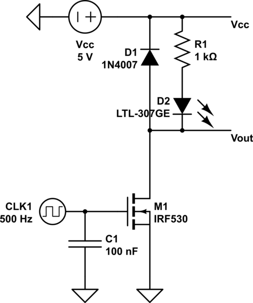
schematic

simulate this circuit – Schematic created using CircuitLab

\$\endgroup\$
4
  • \$\begingroup\$ Is you clock switching from 0v to 5v also? \$\endgroup\$
    – HandyHowie
    Commented May 31, 2018 at 13:15
  • \$\begingroup\$ And the two voltage levels who differentially give 3.4 volts are??? \$\endgroup\$
    – Andy aka
    Commented May 31, 2018 at 13:30
  • 1
    \$\begingroup\$ I suspect your MOSFET isn't being fully switched on if you're only getting 3.4V on Vout. \$\endgroup\$ Commented May 31, 2018 at 13:32
  • \$\begingroup\$ @HandyHowie The clock is 5v, the mosfet is open at 1V according to datasheet. \$\endgroup\$
    – 7E10FC9A
    Commented May 31, 2018 at 13:46

2 Answers 2

2
\$\begingroup\$

The conventional way to use a scope to measure the voltage across the R1/D2 combination in your schematic is to use two probe channels (ie Chan A and Chan B). One probe goes to each end of the combination. Then setup the scope to show A + (B inverted). This ends up showing A-B as the scope waveform.

Modern day digital scopes may have more sophisticated "math" functions that can be performed including the difference between the two channels.

\$\endgroup\$
2
  • \$\begingroup\$ Thanks for the info, but in this case the high side of R1 is always 5V, so it's the same as just measuring the low side. I tried, the result is the same. \$\endgroup\$
    – 7E10FC9A
    Commented May 31, 2018 at 13:44
  • 1
    \$\begingroup\$ Measuring the low side just shows the voltage relative to GND. Your question was all about how to directly measure and show voltage across components that were not connected to GND with a scope that has a GND reference connection. \$\endgroup\$ Commented Jun 1, 2018 at 13:19
0
\$\begingroup\$

Add 1k or less pullup from drain to 5V will get you 5V out .

100 Ohm pullup will do the some and a 100 load will drop that to 2.5V but needs to be 1/2W rating.

\$\endgroup\$

Your Answer

By clicking “Post Your Answer”, you agree to our terms of service and acknowledge you have read our privacy policy.

Not the answer you're looking for? Browse other questions tagged or ask your own question.