1
\$\begingroup\$

I'm trying to build a unit which will convert mains voltage (230vac) to approx 80vac. I have a similar product which I know works for my propose - but it works in a way I don't quite understand. There is a resistor before the output/load and another one in parallel to it.

Here is a diagram of how it looks, with the switch and fuse removed. I've used a bulb to represent output/load. The transformer has a primary coil of 220V and two secondary coils of 24v.
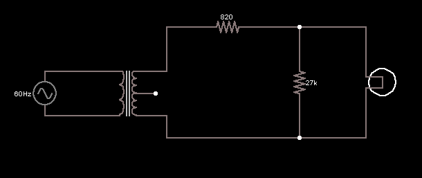
enter image description here

Why has this been done? What advantage does it have over not having the resistors?

EDIT1: The two secondary coils are connected, presumably to make one large coil.

EDIT2: The circuit will be used to power an A4 sample of Smart Glass, which will need around 2W (defiantly no more than 5W). The circuit does have a switch, which I was surprised to find was placed in the 80V circuit. (ie after the transformer)

\$\endgroup\$
2
  • 3
    \$\begingroup\$ What is the real load? (Made up questions get made up suitable answers alas) What is the output Wattage? 2 x 24VAC <> 80 VAC. Something is wrong. Presumably 230 VAC in and one primary winding only. With 820 ohms as shown Pmax out at 48 VAC RMS is about 0.7 Watt. Is that what you'd expect? And Vout will be 24 VAC with the other half dropped across the 820 R resistor. \$\endgroup\$
    – Russell McMahon
    Commented Aug 14, 2012 at 15:04
  • \$\begingroup\$ I've added the what the load is into the question. \$\endgroup\$ Commented Aug 15, 2012 at 11:54

1 Answer 1

3
\$\begingroup\$

The 820 ohm is almost certainly for current limiting.

Without knowing more about the circuit it powers it's hard to be exact about the 27k, however, I think it may be to present a minimum load to the secondary to limit light or no load voltage (possibly to discharge any filter caps also and/or related to PMOS turn on battery/AC switch circuit to pull gate back to ground)
This is often used if the following circuit has no proper regulation (i.e. linear or switch mode)

\$\endgroup\$
5
  • \$\begingroup\$ I've added some info to the question, about what load. Will the resistors change the voltage going to the sample glass? When I used falstad's circuit simulator it does, and the voltage creeps up. Could you tell me why that happens? \$\endgroup\$ Commented Aug 15, 2012 at 11:49
  • \$\begingroup\$ Ah, so it's a pretty simple (probably current driven, but can't be sure without knowing the type of smart glass) load as expected, the resistors make complete sense then. The voltage will depend on how much current the load draws, the more current the less voltage, with max power in the load at half voltage. The voltage in Falstad should reach a steady state unless the load is changing, so it may be that you just didn't run the sim for long enough. \$\endgroup\$
    – Oli Glaser
    Commented Aug 15, 2012 at 12:09
  • \$\begingroup\$ Having the switch in the lower voltage side is better for the switch and less dangerous for the user of a fault occurs. \$\endgroup\$
    – Oli Glaser
    Commented Aug 15, 2012 at 12:12
  • \$\begingroup\$ Thanks. How should I work out the rating needed for the transformer and for the resistors? \$\endgroup\$ Commented Aug 15, 2012 at 12:14
  • \$\begingroup\$ You need to specify your load (voltage, current) and then calculate accordingly. If it's not a simple load (e.g. digital circuit) then a regulator would be best. \$\endgroup\$
    – Oli Glaser
    Commented Aug 15, 2012 at 12:24

Your Answer

By clicking “Post Your Answer”, you agree to our terms of service and acknowledge you have read our privacy policy.

Not the answer you're looking for? Browse other questions tagged or ask your own question.