0
\$\begingroup\$

I've been through the HopeRF95W datasheet a couple of times; some parts less and some parts more.

The Payload Data Extraction from FIFO on page 36 is really very clear and concise.

Once the FifoPtrAddr is set to the end the written segment on the buffer (using FifoRxCurrentAddr), we check the number of bytes (NB) received, loop through that number and read the RegFifo; which is an 8bit register, that NB of bytes times.

This github implementation follow this as well:

uint8_t currentAddr = ReadRegister(REG_FIFO_RX_CURRENT_ADDR);
uint8_t receivedCount = ReadRegister(REG_RX_NB_BYTES);
*p_length = receivedCount;

WriteRegister(REG_FIFO_ADDR_PTR, currentAddr);

for(int i = 0; i < receivedCount; i++) {
    payload[i] = ReadRegister(REG_FIFO);
}

All clear and easy to understand. I am only curious how the SX1276 knows to load the next 8 bits of the FIFO into the RegFifo by simply looping through it?

Is it one of those things where a read triggers some internal event/mechanism on the chip?

My lack of understanding here is probably just lack of experience, since my training and experience is in python.

I am also curious whether this payload extraction procedure is the typical FIFO implementation, or are they always chip dependent?

\$\endgroup\$
2
  • 1
    \$\begingroup\$ Read side effects are not at all uncommon for data fifos, or even single data registers. \$\endgroup\$ Commented Jun 22, 2018 at 4:02
  • 1
    \$\begingroup\$ It will be. This is often how FIFOs work. Not always, but it's not unusual either. \$\endgroup\$ Commented Jun 22, 2018 at 5:05

2 Answers 2

1
\$\begingroup\$

If you refer to the Semtech SX1276 datasheet, this information is pretty clear, at least in the version I have currently. https://www.semtech.com/uploads/documents/DS_SX1276-7-8-9_W_APP_V6.pdf. Should this URL be dead in future, just search for Semtech SX1276 Datasheet Version 6 (or greater).

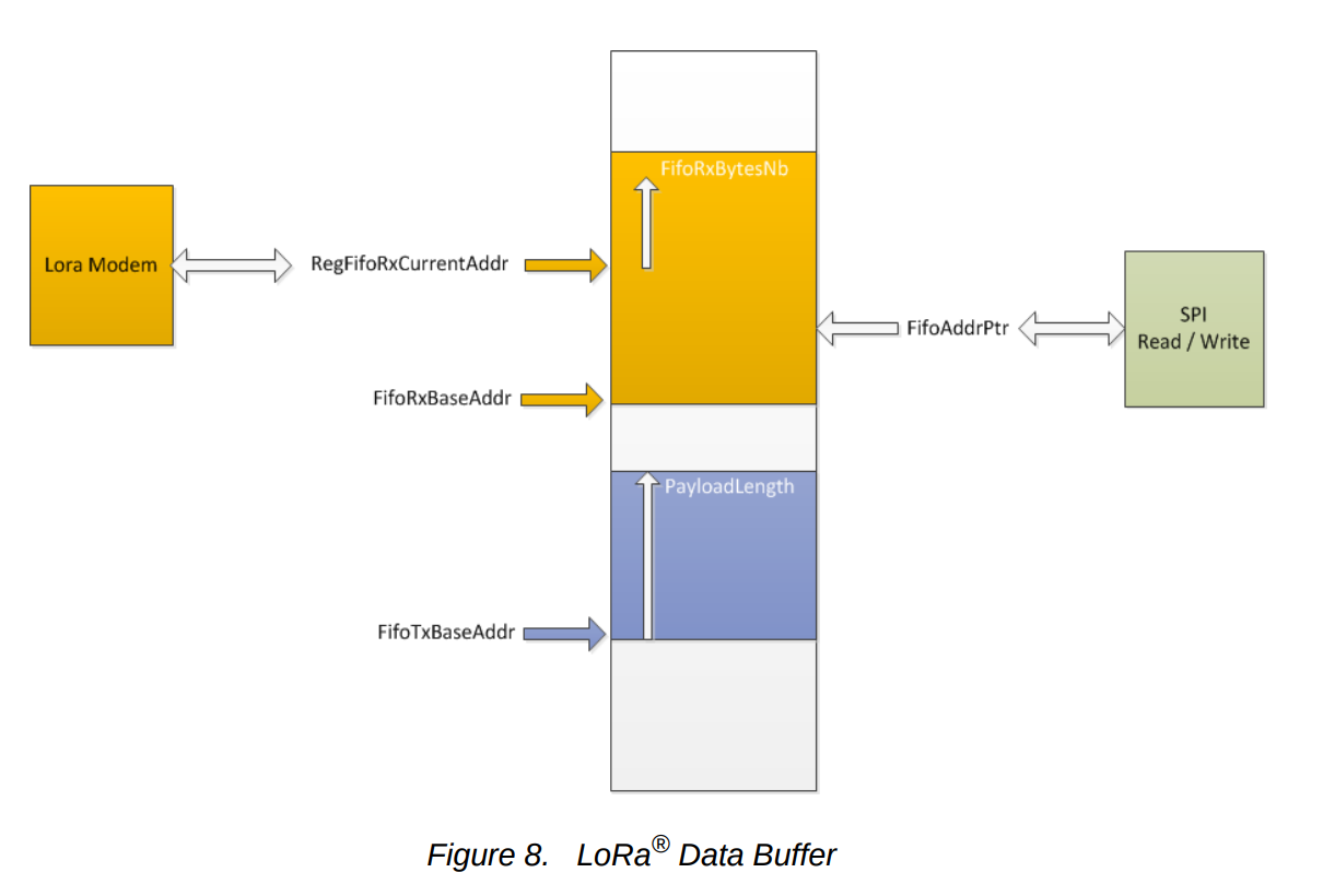
Section 4.1.2.3. gives a really good diagram of how the FIFO is addressed: 4.1.2.3. Figure 8. LoRa® Data Buffer Register interractions with FIFO

When interacting with the FIFO via the SPI protocol, the SX1276 uses the FifoAddrPtr register to choose which byte to return. You can write to this register (its address is 0x0D) to set the address in the FIFO you wish to read and write to when addressing to the FIFO register (address 0x00).

Further down in the document, under Principal of Operation we see:

The FIFO data buffer location to be read from, or written to, via the SPI interface is defined by the address pointer RegFifoAddrPtr. Before any read or write operation it is hence necessary to initialize this pointer to the corresponding base value. Upon reading or writing to the FIFO data buffer (RegFifo) the address pointer will then increment automatically.

The key detail to your question is

the address pointer will then increment automatically.

Whenever you read or write from the RegFifo (address 0x00), the pointer register RegFifoAddrPtr (address 0x0D) is incremented. When you next read or write, you are automatically interacting with the next address in the FIFO. Hope this helps.

\$\endgroup\$
0
\$\begingroup\$

At the lowest levels of the FIFO implementation, there is an address (pointer value) and a write enable and read enable. I am assuming, without seeing it, the function ReadRegister() knows how many were written, and increments the address pointer each time it reads.

As far as typical FIFO implementations, in the simplest form it is nothing more than "write some data incrementing the write pointer each time; and, then, read data to a maximum of read pointer = write pointer" (pointer = address). Could be implemented as a circular buffer, could be "reset pointers to 0" before next data is written, but, in the end, as a user, it should behave the "same" and be independent of the device. Data sheet/user's guide should tell you about any details related to using it.

They are also used in HW design (i.e. SW doesn't have access to it) for other things such as elastic buffers... e.g. accept a burst of data that arrives faster than it can be processed and/or transmitted. These are sized for the communication protocol, and have limitations on them such as max burst size, minimum IDLE time in between bursts, etc. In this case, as a SW person, upstream on the transmit side, you might need to write your SW accordingly.

\$\endgroup\$
3
  • \$\begingroup\$ ReadRegister is a function in the WiringPi library. It does nothing more that return the bits of a register. It does no incrementing at all \$\endgroup\$ Commented Jun 22, 2018 at 9:36
  • \$\begingroup\$ I am not unfamiliar with FIFO in so much as that bit of code looked like magic. I expected some pointer arithmetic! \$\endgroup\$ Commented Jun 22, 2018 at 9:37
  • \$\begingroup\$ Correction: ReadRegister uses the wiringPiSPIDataRW from WiringPi but neither does any pointer arithmetic \$\endgroup\$ Commented Jun 22, 2018 at 10:37

Your Answer

By clicking “Post Your Answer”, you agree to our terms of service and acknowledge you have read our privacy policy.

Not the answer you're looking for? Browse other questions tagged or ask your own question.