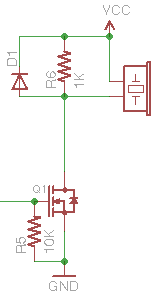
Is this a proper way to connect a piezo buzzer to microcontroller pin? Is there anything that could be improved in the sense of robustness and power consumption? How do i select D1?

Is this a proper way to connect a piezo buzzer to microcontroller pin? Is there anything that could be improved in the sense of robustness and power consumption? How do i select D1?
You can probably stand to increase your pull-down resistor value significantly. (try 100k or 1M) - As far as the 1K resistor goes, as this provides a discharge path for the piezo's capacitance, its value will be determined by the size of the piezo, as well as the frequency range you intend to drive it at. A higher value will be less lossy, but may not provide adequate discharge for the piezo if it is very large or you intend to drive it at a very high frequency (where a quick recovery is necessary) This is easy to estimate if you know the capacitance of the buzzer.
D1 should be a fast diode, any schottky type should do fine.
Depending on how loud you want the buzzer, you can add a resistor in series with the buzzer itself. I would start with low resistance values (10s of ohms) and work up to something you're happy with. Again you're taking a loss, but if you can't adjust your drive voltage, this is an option. A capacitor in series with the buzzer is also an option, to provide a power limitation, as well as change the character of the tone.
Not all piezoelectric buzzers are made equal,
Basically you have the very simple ones, those are only a sort of a small piezoelectric speaker, (like those old Motorola tweeters, all plastic case, no magnet), beware; those are destroyed by DC, so use a capacitor (0.01 uf) to avoid dc going through the transducer, and make sure that you are feeding the beast with some square or sinusoidal wave, and.. Then the piezo buzzers that have a built-in oscillator/driver circuit, that drive the piezoelectric element, with those you must have the specs of the buzzer, but I have found that most of them behave well with 5 Volts dc. mass production have made them dirt cheap.
A simpler way which I have used a lot is to directly connect the piezo in bridged mode, using two I/O pins. This technique is only to be used with the much cheaper bare piezo elements, not buzzers which have a fixed frequency driver built in. For the latter, the questioners circuit should be used.
By definition, a piezo will not output much more voltage than is used to drive it, and the protection diodes on the port will protect the MCU from any spikes.
Most PWM modules in modern MCUs can be configured to use two output pins; one non-inverting, and one inverting. This gives twice the supply voltage across the piezo, peak to peak, which gives much better volume and avoids the slow discharge one would get with the single-ended driver circuit above.
Also, this way of doing it removes all the ancillary components. It does require a little coding to set up the PWM to output the correct frequency, but if you want full control of the output frequency and volume, it's very cheap. It is a commonly used technique, often used in musical birthday card circuits for example.