6
\$\begingroup\$

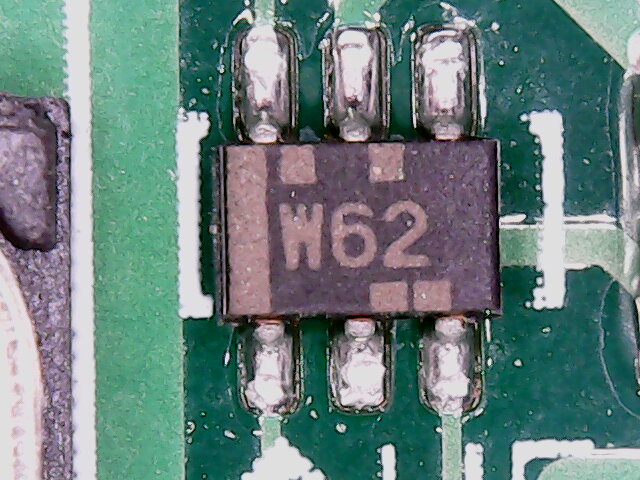
W62 chip

QUESTION: What is this component? RESOLUTION: Equivalent part is SN74LVC2GU04DCKT normally code "CDK" This appears to be specially "Wacom" branded for obscurity. Question below for historical context.

I have a component from a Wacom DTK-2100 digitizer board that I'm struggling to identify. It is presently situated in a fully functional board.

Some context information, Top middle pin is 5V, bottom middle pin is 0V The top right and bottom left pins have no resistance between them, in a functional circuit, the Top left had 2.86V, and the bottom right had 2.2V, the Bottom Left/Top Right had 1.75V.

Any suggestions on what I could try replacing this with in the event that it cannot be identified? Looking up the short code brings be to an SOT323 package, and 3 pins simply won't do.

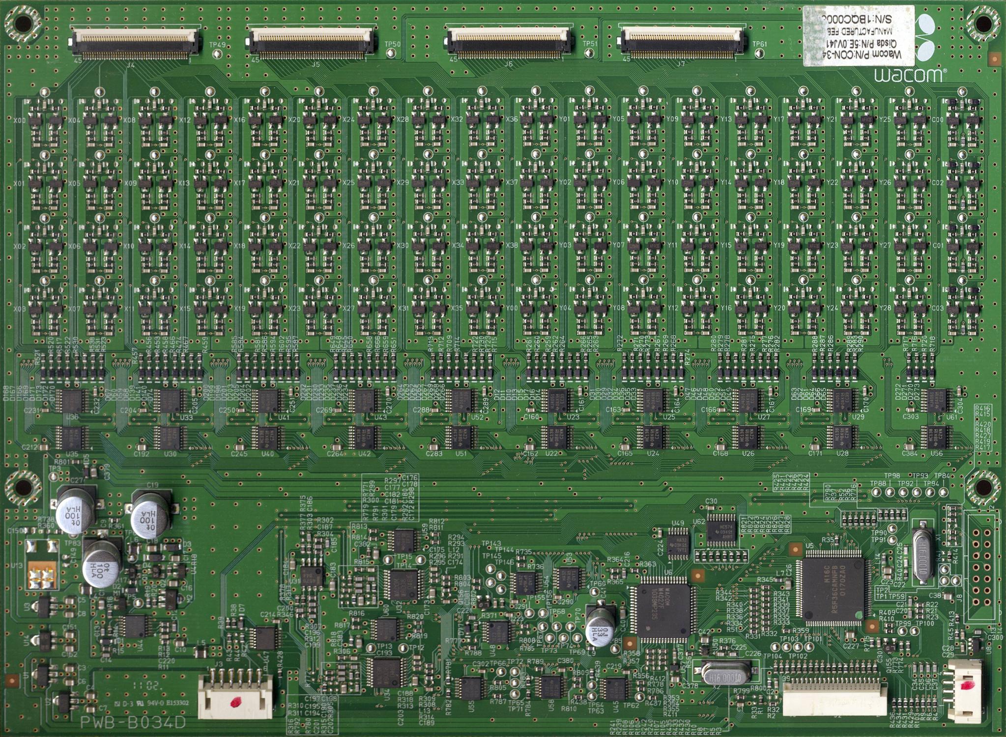
For more context here is a scan of the board from someone else. This component is in the Bottom Right quadrant between the horizontal quartz crystal and the WACOM QFP component. It is marked U50 on the PCB.

Current presumption: I took a look at a same generation model and the component was a "CDK" dual inverter as anticipated by one of the commenters. Link to datasheet: http://www.ti.com/lit/ds/symlink/sn74lvc2gu04.pdf

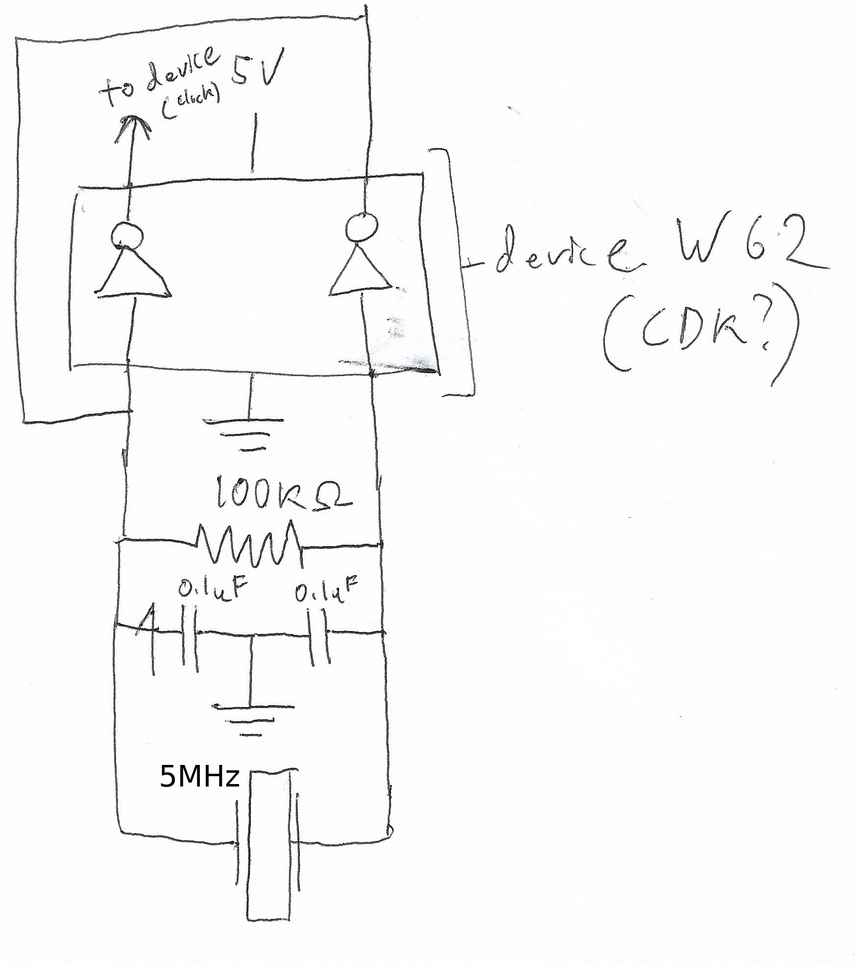
I included a more complete schematic of the circuit now that I'm reasonably sure of what it is and knowledgeable of the neighboring components. It appears Wacom rebranded the device to obscure its function in higher end models.

(Side note, for those attempting digitizer repair on DTK-2100 boards, if there is no -4V line, in the center of the board (should have +5V +4V and -4V rails mid board, and +5, +5 and +3.3 rails along the edge of the board) then most likely this component is the defective culprit as the clock is needed to generate an inverting signal.)

Wacom Board Scan

Circuit Diagram

\$\endgroup\$
11
  • 2
    \$\begingroup\$ An partially reverse engineered schematic around that could help. My guess would be some opamp. \$\endgroup\$
    – PlasmaHH
    Commented Oct 9, 2018 at 13:09
  • 2
    \$\begingroup\$ Ian - Welcome to the site :-) Please see these guidelines regarding component identification questions. \$\endgroup\$
    – SamGibson
    Commented Oct 9, 2018 at 13:19
  • 2
    \$\begingroup\$ Added hi-res context photo per guidelines. I will be grabbing more data as I go this morning. \$\endgroup\$ Commented Oct 9, 2018 at 13:39
  • 1
    \$\begingroup\$ Can you follow the traces on the pins to see what they're connected to? That's usually one of the easiest ways to figure out, if not specifically what the thing is, what it's doing. \$\endgroup\$
    – Hearth
    Commented Oct 9, 2018 at 16:09
  • 1
    \$\begingroup\$ Bottom Left and Bottom Right are connected to opposite ends of the nearby quarts crystal, with a 50K Ohm resistor between them, and they each have a teeny capacitor to ground, Top Middle is to a 5V power line, and Bottom Middle is to 0V Ground, Top Right is connected to Bottom Left, and Top Left is connect to the Wacom QFP via a 1000 ohm resistor. Unclear if it is input or output from the QFP. I'm trying to set up my scope and test the quartz crystal atm. \$\endgroup\$ Commented Oct 9, 2018 at 16:29

1 Answer 1

2
\$\begingroup\$

Based on the net connectivity of the unknown circuit element U50, I would strongly believe the component to be a dual inverter. Using an inverter as the active gain element in a Pierce oscillator, is very common for non-RF applications.

You can test the basic functionality of the component by over-driving pin 3 (based on your hand drawn schematic). Connecting pin 3 to ground, pin 4 should output high. The other gate in package should also perform its correct logical operation.

Aside: The 2 load capacitors (on either side of the crystal) would most likely be in the range of 16 to 64 pF depending on the crystal used. Very unlikely to be 100 nF.

\$\endgroup\$
4
  • \$\begingroup\$ You are correct about the dual inverter, I've marked your formal answer as correct. However, the capacitor is a 0603 package capacitor at 0.1uF for sure. I measured with a mediocre capacitance meter and it tests around that range in deactivated circuit. Its output is just the clock, so maybe it was just cheaper to use standard SMT components with higher capacitance? Perhaps because R2 is <1 Ohms? Assuming this circuit: bit.ly/2CkEeBO Thanks. \$\endgroup\$ Commented Oct 16, 2018 at 17:10
  • 1
    \$\begingroup\$ It would be atypical for the 2 load capacitors to be 100 nF. The power-supply bypass capacitor could certainly be. Capacitor measurement can be problematic in circuit. If your capacitance meter can correctly measure the 0V capacitance of a generic signal diode (like a 1n4148) ~ 4 pF, its likely valid. Of course best case is to measure the component out of circuit. \$\endgroup\$
    – sstobbe
    Commented Oct 16, 2018 at 17:45
  • \$\begingroup\$ It is also in line with the packaging of the capacitor and standard components (i.e. all 0603 capacitors on mouser are 0.1uF only tolerance and temperature etc vary), and the circuit continued to function once I swapped it with another capacitor. I don't know the logic, but I know that it works and that's an accurate representation of the circuit. My cap meter is not super accurate, but it reads max when I test it on the 20nF setting, and it reads ~50-200 when I have it on the 200nF and 2uF setting and 0 on higher settings. \$\endgroup\$ Commented Oct 16, 2018 at 23:09
  • 1
    \$\begingroup\$ That is fascinating a 100 nF cap has an impedance of 100 milliOhms at 16 MHz. Perhaps that's why the inverter failed. Happy to hear it works. \$\endgroup\$
    – sstobbe
    Commented Oct 17, 2018 at 0:24

Your Answer

By clicking “Post Your Answer”, you agree to our terms of service and acknowledge you have read our privacy policy.

Not the answer you're looking for? Browse other questions tagged or ask your own question.