1
\$\begingroup\$

I stopped using BJTs for a while and now I can't figure out why this configuration does not give me a 12 V PWM at the gate of the MOSFET? I am only getting slightly more than my PWM voltage about 4.2 V.

I have tried resistors at the gate to limit current and different resistors at the PWM for some input impedance but nothing. If I am not mistaken, when the top transistor is on it should effectively close that "switch" and I should get my 12 V at the gate. Maybe I've spent too much time playing with MOSFETs and I have forgotten how BJTs work.
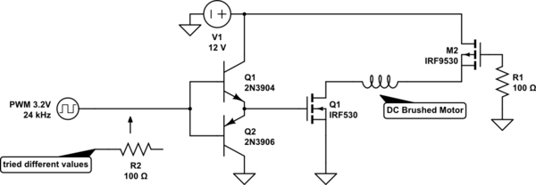
schematic

simulate this circuit – Schematic created using CircuitLab

\$\endgroup\$
1
  • \$\begingroup\$ Try adapting this. It's close. \$\endgroup\$
    – jonk
    Commented Nov 2, 2018 at 5:10

1 Answer 1

4
\$\begingroup\$

Your BJTs are configured as followers so the gate signal will be smaller than the drive by a diode drop each way. Perhaps add a common emitter amplifier between the drive signal and Q1/Q2 to boost the amplitude to near 12 V peak to peak.

\$\endgroup\$
1
  • 2
    \$\begingroup\$ oh I see, I remember that term from a couple of semesters ago. I think I need to hit the textbooks for a refresher to see how that is so. \$\endgroup\$ Commented Nov 2, 2018 at 4:38

Your Answer

By clicking “Post Your Answer”, you agree to our terms of service and acknowledge you have read our privacy policy.

Not the answer you're looking for? Browse other questions tagged or ask your own question.