2
\$\begingroup\$

I am building a battery management system (BMS) with my 10s2p battery pack using passive balancing. Passive balancing is when you put a resistor in parallel with your battery cell to discharge a certain cell so that you can maintain all your cells to be the same voltage.

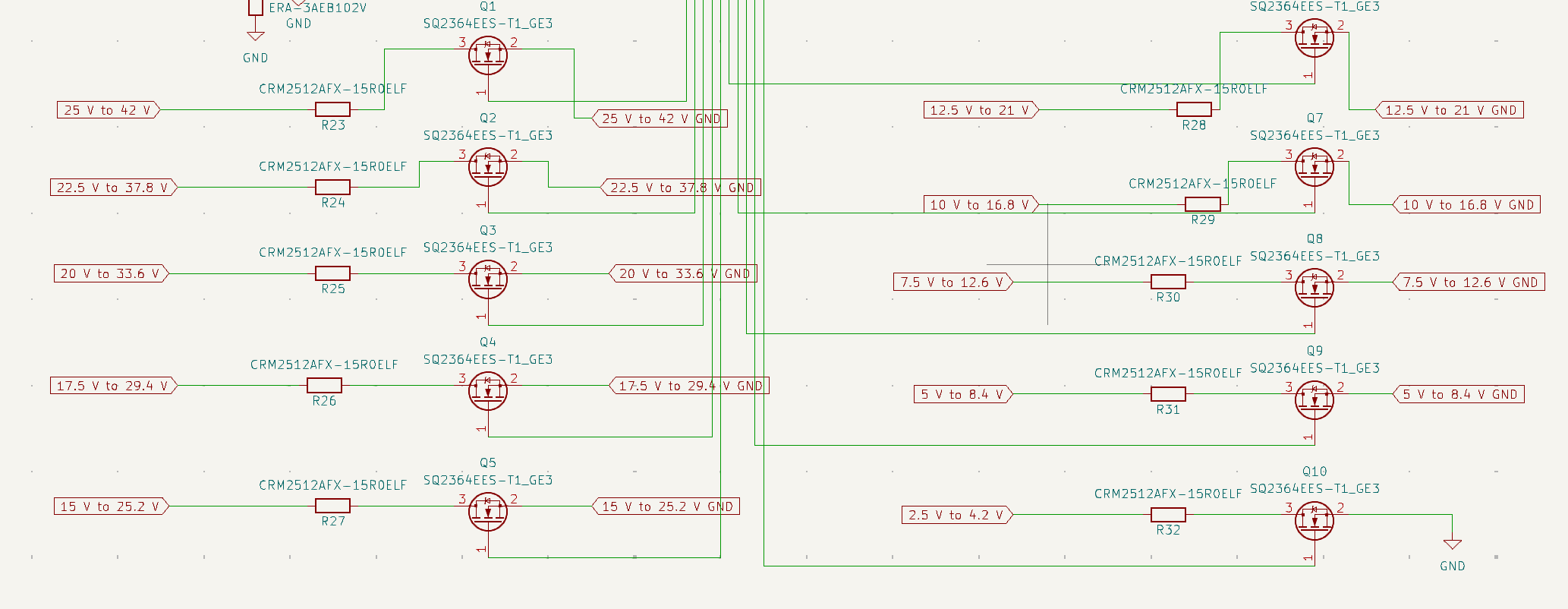
In order to turn on each cell individually I am planning on using an N channel MOSFET with a resistor in series that are connected to the positive and negative of my battery cell. Here is a picture of the schematic:

enter image description here

The problem I am having is I can't figure out a way to turn on these MOSFETs with a 3.3 volt microcontroller. I considered using a basic charge pump bootstrap circuit, but with my max voltage of 42 Volts the gate to source / source to gate voltage always ends up higher than my MOSFET max VGS rating. Not many MOSFETS have a VGS greater than 20 volts.

For instance if I did a charge pump bootstrap circuit at the 42 Volt max rail, then when I make the MOSFET gate to be 0 volts to turn off the MOSFET, then the gate to source voltage would be 42 volts - 4.2 volts (Voltage of 1 cell) = 37.8 volts at the source which would make the VGS be 0 V - 37.8 V = -37.8 V which is much higher than the rated VGS for most MOSFETs.

How can I accomplish my simple task of turning on and off these high voltage MOSFETs with 3.3 volt microcontroller. Is there a better way to do this than what I am trying to do? I am doing this as a learning experience so I would prefer to not use an integrated circuit.

\$\endgroup\$
10
  • \$\begingroup\$ Hi So how are the batteries connected together? \$\endgroup\$
    – Tyassin
    Commented Nov 30 at 21:41
  • \$\begingroup\$ @Tyassin It is a 10s battery. So 10 cells connected in series. \$\endgroup\$
    – Trev347
    Commented Nov 30 at 21:43
  • 1
    \$\begingroup\$ OK. How about using switches / relays / solids state relays, instead of transistors? \$\endgroup\$
    – Tyassin
    Commented Nov 30 at 21:48
  • 3
    \$\begingroup\$ With this unusual arrangement, I think the way to go is actually to use a photovoltaic MOSFET driver, like a VOM1271. Or just replace your MOSFETs entirely with small, cheap solid-state relays, like CPC1017s. \$\endgroup\$
    – Hearth
    Commented Nov 30 at 22:13
  • 2
    \$\begingroup\$ The common solution is to use gate drivers with built-in floating level-shifters like the BQ78350 BMS controller ti.com/tool/BQ76940EVM \$\endgroup\$
    – D.A.S.
    Commented Nov 30 at 22:17

1 Answer 1

4
\$\begingroup\$

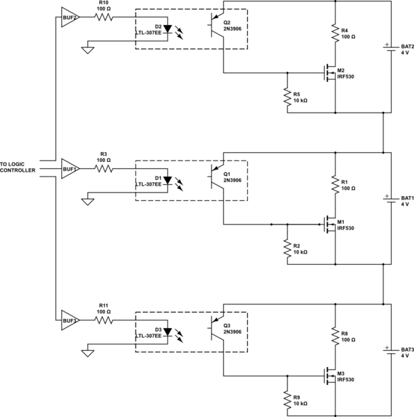
A battery management system (BMS) usually has one discharge path in parallel with each cell, comprised of a switched resistor. This means that the voltage the switch sees when it is OFF is just the voltage of one cell (about 4V maximum), not the voltage of the entire battery pack. Thus, you can use a low-voltage MOSFET or BJT as the switch. There are many low-voltage MOSFETs are available with low gate-source threshold voltage, for example: 2SK1580, rated at Vdss(max) =16V, Vgs(max)=+/-16V, Idrain (max)=100mA, and can be driven from 3V logic.

The remaining problem is how to drive each switch. You could use an opto-isolator to isolate the logic signals from your MCU, and use the voltage of each cell to drive the gate of the MOSFET. One way of arranging this is shown in the figure below. This shows how to connected three (3) cells in series, as the battery voltage increases just keep adding more cells in series, and adding the discharge circuit in parallel with each cell. There will be a limit to how many cells you can put in series; that limit is determined by the maximum voltage that the opto can tolerate between its LED and its output transistor; this is usually a few hundred voltages at least, so you should have no problem when charging a string comprised of 10 cells connected in series.

Of course, you have to select the components carefully. For example, the bypass resistors (R1, R4, R8) must be selected to ensure the correct current is bypassed from the cell without excessive heating. Generally, the larger the battery capacity (Amp-hours) then the higher this bypass current. When that is selected to suit your battery, then selecting the MOSFET and the other components should be a simple matter.

schematic

simulate this circuit – Schematic created using CircuitLab

The default state of the circuit above (when no power applied to the opto LED) is that the current bypass is OFF; you may decide, for safety reasons, to have the opposite. In that case, when the LED is OFF the MOSFET is ON. That is quite simple to do by changing the gate drive of the MOSFET.

\$\endgroup\$
1
  • 1
    \$\begingroup\$ I agree with Fabio that the solution is to use an opto-isolator so that your MOSFET gate is not tied to the ground of the entire battery pack, but rather only the ground of the 1 cell. I decided to use the CPC1002N which is a solid state relay \$\endgroup\$
    – Trev347
    Commented Dec 1 at 14:31

Your Answer

By clicking “Post Your Answer”, you agree to our terms of service and acknowledge you have read our privacy policy.

Not the answer you're looking for? Browse other questions tagged or ask your own question.