1
\$\begingroup\$

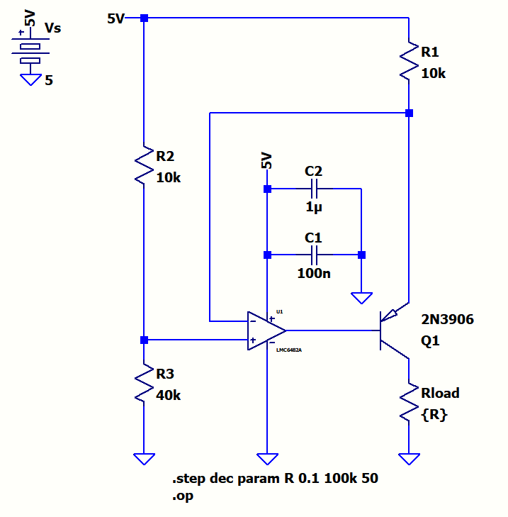
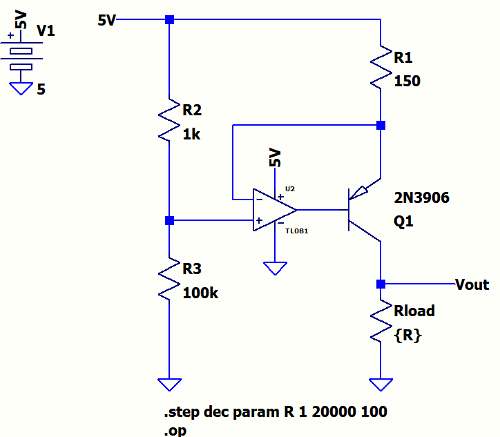
I'm not into the current source subject much, but the following circuit provides constant current to the load up to around 500 Ohm:

original schematic

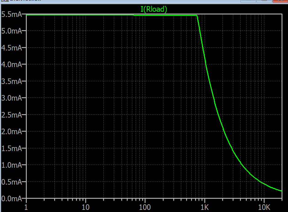
Here below is the plot of Rload versus Iload:

plot of Rload vs. Iload for original schematic

How can this circuit be modified to obtain the constant current source upto 20k?

Edit:

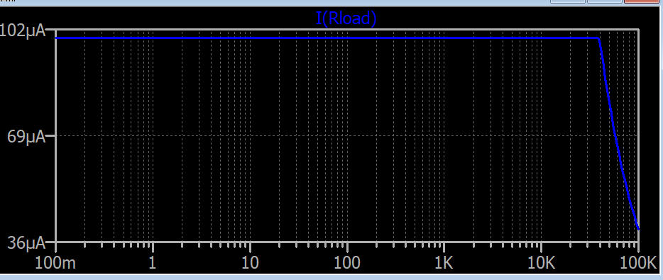
After reading the answers I changed the circuit to the following one:

updated schematic

plot of Rload vs. Iload for updated schematic

\$\endgroup\$
6
  • \$\begingroup\$ What's the current range you were looking for? Do you need more range than is provided by \$5\:\text{V}\$? It's quite possible to design a circuit that will achieve control ranges of hundreds of volts from an opamp that can only handle a few dozen volts with just a few BJTs around it. But if you are good with only a few dozens of microamps as a current source, then perhaps this is all you need. \$\endgroup\$
    – jonk
    Commented Nov 8, 2018 at 21:22
  • \$\begingroup\$ Oh, yeah. Now I remember some of the related questions. Thanks for connecting the dots for me. So this is about a freely turning potentiometer which over a certain tiny range of angle might short out both ends of the potentiometer so that all three connections are effectively joined together. \$\endgroup\$
    – jonk
    Commented Nov 8, 2018 at 21:50
  • \$\begingroup\$ How will you be measuring the wiper position? How will you calibrate that measurement? If you use a current-limited voltage source, you can pick off the voltage at the wiper. When it shorts the supply, the current limiter drives the output voltage downward, rapidly. But this should be okay, since you are nearing the place where you'd read zero, anyway. If you use a current source, it will supply that current but with the short the voltage output will again get very close to zero. Either approach works. It's just a matter of what you are more comfortable doing, I suppose. \$\endgroup\$
    – jonk
    Commented Nov 8, 2018 at 21:56
  • \$\begingroup\$ I see that they provide for both the voltage/current source wires as well as sense wires. So you really should be using a differential measurement method as they are providing you with all the needed tools for that. \$\endgroup\$
    – jonk
    Commented Nov 8, 2018 at 21:59
  • \$\begingroup\$ @jonk The wiper position is the Vout will go to a data acquisition with a very high input impedance. Similarly the Vref will go to another channel of the data acquisition device, So I will take the ratio Vout/Vref and relate it to the angle. I was thinking to limit by a series resistor as in my linked question and not using a constant current source. In terms of linearity do you see any problem in this ratiometric measurement?: i.sstatic.net/JoKxV.png \$\endgroup\$
    – user1245
    Commented Nov 8, 2018 at 22:00

3 Answers 3

1
\$\begingroup\$

Reduce the current and/or increase the supply voltage.

A quick calculation shows you that 5.5mA * 20k = 110V. That would be a bit hard to obtain with a 5V supply.

The current is set by the voltage across. R1.

\$\endgroup\$
5
  • \$\begingroup\$ I prefer to reduce the current to around 0.2mA . \$\endgroup\$
    – user1245
    Commented Nov 8, 2018 at 19:05
  • \$\begingroup\$ But after a limit i couldn't make it work. I want to feed a far away 20k poti with a stiff current source. By using a 5V supply. \$\endgroup\$
    – user1245
    Commented Nov 8, 2018 at 19:08
  • \$\begingroup\$ @user164567 this circuit is referred to Vdd and you are using a very low voltage drop, the op-amp has to be able to operate with inputs near the rail. But if it is operating, and the maximum output voltage works for you, all you need to do is increase R1. \$\endgroup\$ Commented Nov 8, 2018 at 19:33
  • \$\begingroup\$ Please see my edit. How can I improve this circuit for a voltage stability or noise. I added caps on positive rails for decoupling. But in some circuits I see diodes and caps at inputs. \$\endgroup\$
    – user1245
    Commented Nov 8, 2018 at 20:38
  • \$\begingroup\$ There is little to do here for stability. Add a cap between Vdd and the + input of the op-amp to reduce circuit noise, and perhaps a small cap across the BE junction if the op-amp presents too low of a phase margin in this configuration. But if you are carrying 0.1µA via a long cable to drive a relatively high-impedance load, the noise injected into the cable itself would be a bigger concern. \$\endgroup\$ Commented Nov 8, 2018 at 21:21
1
\$\begingroup\$

If you pass 5.5mA from a 1K ohm load, then Vout is 5.5mA * 1K =5.5volt, and circuit saturate before reaching this load.

your circuit works with 5 volt supply and Vcc = R1 * 5.5mA + V_ce + R2 * 5.5mA

for 5.5mA output and RL=20K, you need a supply voltage 20K*5.5mA+..+..> 100V

You need a supply voltage bigger than 100V, No opamp can handle this voltage and this circuit not works a for 20k load.

You can use this circuit instead: refference: http://www.ecircuitcenter.com/Circuits/curr_src1/curr_src1.htm
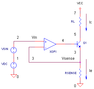
http://www.ecircuitcenter.com/Circuits/curr_src1/curr_src1.htm

opamp power is 5V,

Resense = 500 ohm

for 5.5 mA output -> vin(VDC) 2.75 volt

VCC = 20k * 5.5ma + 500 * 5.5ma + V_CE ~ 120 volt is ok and Q1 should handle 100 volt (minimum (120-112.75) volt!)

\$\endgroup\$
2
  • 1
    \$\begingroup\$ if you need 0.2mA, change the 5V supply with 10 volt supply(in your post), and change R1 to 10K ohm, and choose R2, R3 with solving this equation (10-10*R3/(R2+R3)) = 10k * 0.2mA \$\endgroup\$
    – M KS
    Commented Nov 8, 2018 at 19:41
  • \$\begingroup\$ Thanks, I set R3 to 40k and R2 to 10k and it worked. It even worked with 5V with 0.1mA constant current. In reality for such application does the type of op amp matter. I have at the moment TL272 opamp. I want to have this 0.2 or 0.1mA constant current as stiff as possible and with less noise possible. Any hint on the type of opamp for better precision(dual or single supply ect.)? \$\endgroup\$
    – user1245
    Commented Nov 8, 2018 at 20:13
1
\$\begingroup\$

Your circuit is not a good one, the TL081 has a large maximum offset voltage in comparison to the 49.5mV feedback signal and it is not guaranteed to work with Vin at the positive rail (though it will typically do so at room temperature). Better to use a rail-to-rail input/output op-amp with reasonable Vos.

In any case, to decrease the current simply increase the emitter resistor to 49.5mV/Iout. So 249\$\Omega\$ will give you about 200uA. You might have to divide the base voltage to the positive rail because the output is certainly not guaranteed to swing close enough to the positive supply to turn the transistor off. But if you use a rail-to-rail I/O op-amp it will work fine. TL272 is not a rail-to-rail op-amp either. MCP6001 would be one (of many) possible choices, but I would suggest increasing R2 to 4.99K and R1 to 1.18K to reduce the Vos effect.

\$\endgroup\$
2
  • \$\begingroup\$ I set R3 to 40k and R2 to 10k and it worked. Also with 5V with 0.1mA constant current. In reality for such application does the type of op amp matter? You already wrote that better to use a rail to rail . I have at the moment TL272 opamp. I want to have this 0.2 or 0.1mA constant current as stiff as possible and with less noise possible. Any hint on the type of opamp for better precision(dual or single supply ect.)? My aim is to use this constant current source for a remote poti. I also have this one rail to rail ti.com/lit/ds/symlink/lmc6482.pdf Would that be a better choice? \$\endgroup\$
    – user1245
    Commented Nov 8, 2018 at 20:16
  • \$\begingroup\$ Yes, the LMC6482 would be a better choice. The type of op-amp does matter if you want it to work. \$\endgroup\$ Commented Nov 8, 2018 at 20:19

Your Answer

By clicking “Post Your Answer”, you agree to our terms of service and acknowledge you have read our privacy policy.

Not the answer you're looking for? Browse other questions tagged or ask your own question.