I'm trying to build a capacitor multiplier to remove ripple from a power supply. The power comes from a dc-to-dc converter (MC34063). The actual load is a circuit that has multiple modes of operation and it takes 2mA to 20mA. Fortunately enough, it works from 12V to 26V so I do not need to regulate the voltage to a fixed value. I only need to remove the ripple.
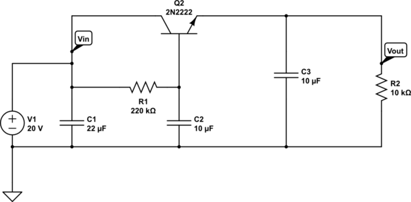
simulate this circuit – Schematic created using CircuitLab
The idea of ripple reduction came from here:
https://www.edn.com/design/analog/4350857/Capacitor-amplifier-reduces-ripple-without-dc-loss
The RC filter is 220k Ohm 10uF with a cutoff frequency of 0.072Hz. C2 is a ceramic cap that has 20V DC offset so probably the real capacity is lower and the cutoff frequency is higher, but it should not matter. The 2N2222 has an absolute minimum hFe=35.
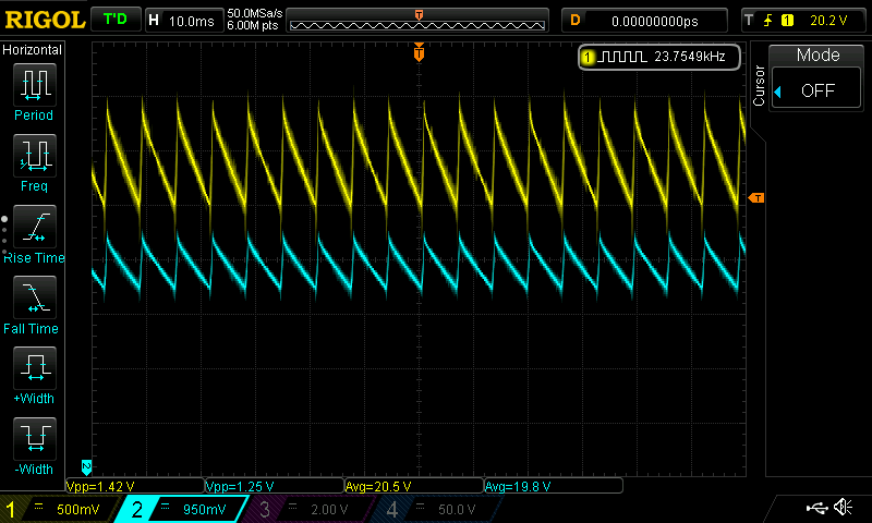
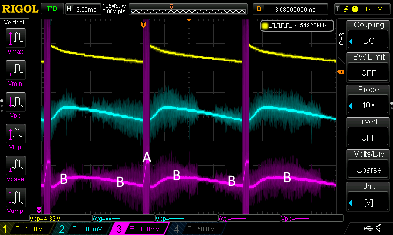
Here is what I have measured:
The original ripple of 1.42V was reduced to 1.25V.
Note: in my original question I zoomed in the time scale too much and I was seeing another ripple that was superimposed on the main signal, this was corrected to the above version.
As far as I understand, the transistor is in common collector configuration, and it inverts and amplifies the error between the actual and the "average" voltage. The above image shows that ripple at Vin and Vout are in phase. There is something fundamentally wrong with my design, I just don't see it.
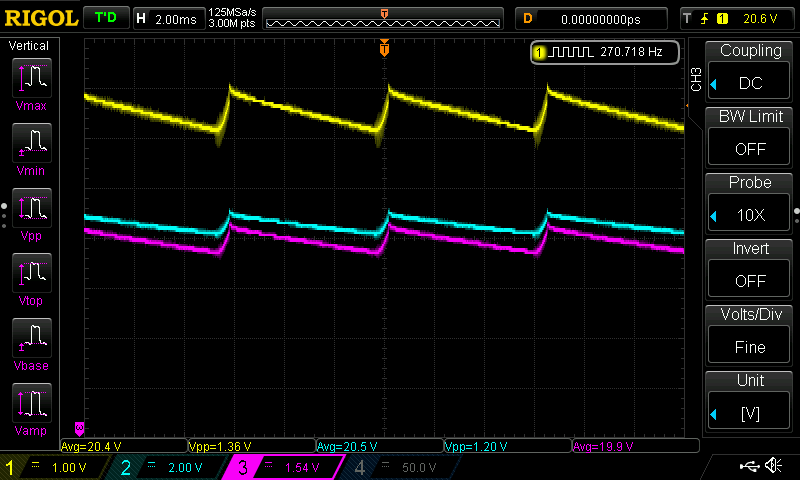
UPDATE This diagram shows: Vin (yellow), V(C2)(blue) and Vout(purple).
The problem seems to be with the voltage at the transistor's base. It should not have 1.2V ripple. I'm still not sure what is happening here.
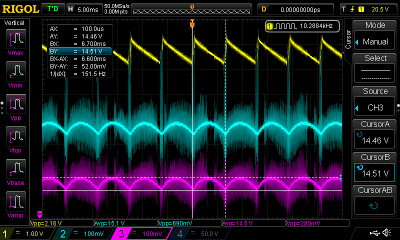
UPDATE: first of all, the transistor was faulty, it had a short between the collector and the base. That is why there was a "problem" with the voltage at the base. Replaced the transistor and changed the circuit to use the suggested voltage divider instead of a single resistor. R1 = 47k and R2 = 220k. If I remove the transistor then there is 16.8V at Vbase.
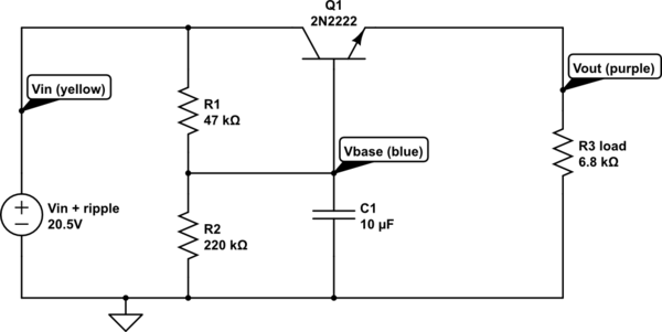
The basic ripple is now reduced from about 2V to 50mV. But a very high frequency oscillation appeared, as glen_geek had foreseen. This circuit is much more complicated than I tought.
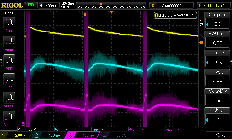
UPDATE - after putting a ferrite bead between the voltage divider and the transistor base, the high frequency noise is still there:
The waveform is changed, it has a bigger spike in it.

