1
\$\begingroup\$

I am using a VCVS in LTSPICE.

I am confused about the command in the Spiceline for using a Table.

I want to use the VCVS as a 1 bit Comparator instead of making a transistor based one.

What will adding the following spiceline for a VCVS in LTSpice do ?

table=(-0.5 0, 0 0, 1.0e-6 1, 0.5 1)

Will it set the output to 0 when the VCVS is input with -0.5, 0 output when it gets 0, 1 output when it gets 1u and one output when it gets 1?

Is this correct ?

Thanks.

\$\endgroup\$

1 Answer 1

1
\$\begingroup\$

Your requirements are a bit odd: you want zero output for -0.5 input, and basically 1V output for anything above zero (1u) input? What do you want to have in between? Linear interpolation? abrupt change in the middle? Hysteresis?

If you're using LTspice, then the best option readily available as a comparator is using the A-devices, in [Digital]. The simplest is the AND, or BUF, with ref=<...> being the threshold voltage, and with td, tripdt, and one of trise+tfall, or tau, or rout+cout, being the temporal aids for the waveform. SCHMITT triggers ar a bit more versatile in that they allow a threshold, vt, and a hysteresis, vh.

You could use a VCVS, or VCCS with proper termination (for better convergence, as per the manual), but table() is a linear interpolation of points, bringing possible discontinuities, which means you risk time step too small errors.

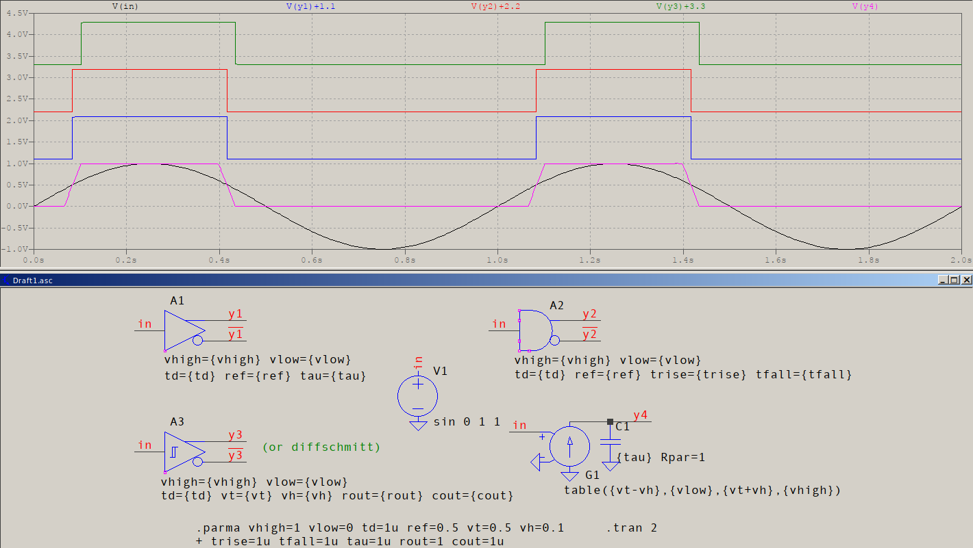
Here are the few presented options:
test

A1 is a BUF, so it uses ref as the reference and tau for smooth RC output, A2 is AND and uses the same ref, with trise/tfall for linear ramp output, A3 is a SCHMITT (use DIFFSCHMITT for differential input), so it uses vt for threshold and vh for hysteresis, while rout/cout control the smooth RC output.

G1+C1 form what you had in mind but, as you can see, it's limited: it needs a minor hysteresis, which needs to be very small compared to the swing, otherwise it linearly interpolates and you get the nice pink waveform, it has no complementary outputs (like the others before), and it needs a sort of a time constant at the output to help smooth out the discontinuities. All in all, you get two elements + two nodes, with drawbacks, compared to one element + two nodes[*] with improvements. Hardly a choice.

[*] If you're using the complementary outputs, then you have one more node, but then, for the G+C version, you also need an inverter of some sort, so you add not only a node, but one more element (at least).

Having said these, for your solution it looks like you need a SCHMITT gate, with vt=-0.25 vh=0.25 (vhigh and vlow are 1 and 0 by default), but this is assuming you want hysteresis. If you want linear interpolation, G+C is the way to go. If you want an abrupt change in the middle, then go for BUF or AND, with ref=-0.25.

\$\endgroup\$
4
  • \$\begingroup\$ Thanks, I am new to LTSpice commands. So my analysis of table, is it correct ?: table=(-0.5 0, 0 0, 1.0e-6 1, 0.5 1) will it set the output to 0 when the VCVS is input with -0.5, 0 output when it gets 0, 1 output when it gets 1u and one output when it gets 1? \$\endgroup\$
    – user4434
    Commented Jan 7, 2019 at 22:19
  • \$\begingroup\$ @sheeple First, step back for a moment and look at your code: when the input is -0.5, the output is zero, but so is when the input is 0. Then the output is 1 when the input is 1u, but so is when the input is 1. You either have two redundant pairs, or you meant for it to behave differently. That's what I meant in my first paragraph. If you simulate this with a triangular waveform, e.g. pulse -2 2 0 1 1 0 2, you'll see that the -0.5V input has no efect. So I'll ask again: what exactly is it you want, and how: hysteresis, linear interpolation, or typical comparator? Use pen&paper if needed. \$\endgroup\$ Commented Jan 8, 2019 at 13:49
  • \$\begingroup\$ I am using this as a 1 bit comparator in an ADC, if that helps \$\endgroup\$
    – user4434
    Commented Jan 9, 2019 at 14:46
  • \$\begingroup\$ @sheeple You can use it wherever you want, but first you must clarify, to yourself, mainly, what is it you want: grab a pen and paper, draw a triangular waveform, and decide what happens at point X when voltage goes from neg to pos, then what after, then at point Y, then when voltage goes from pos to neg, etc. This is something you need to clarify in order to go further, otherwise you, yourself, won't know what you're doing and where you'll be ending. Still, I highly recommend the A-devices instead of a table(), and it's not just me. Have you read all my reply to see why? \$\endgroup\$ Commented Jan 9, 2019 at 18:01

Your Answer

By clicking “Post Your Answer”, you agree to our terms of service and acknowledge you have read our privacy policy.

Not the answer you're looking for? Browse other questions tagged or ask your own question.