1
\$\begingroup\$

(Note: I am aware that crystal and oscillators are two different things but a lot of people use them interchangeably so I am using it in the title.)

My question is about oscillators, all oscillator datasheets mention the output in terms of XXpF. I presume using that pF at the output provides the stability in output, am I correct?

If I want to process the oscillator output stages, what care should be taken in order to acquire a sine wave with as low THD (total harmonic distortion) as possible?

When I say post-processing, I want to convert the unipolar output of oscillator into bipolar levels. I am afraid this can cause a lot of distortion.

Is there an alternate solution?

\$\endgroup\$

3 Answers 3

5
\$\begingroup\$

If I want to process the oscillator output stages, what care should be taken in order to acquire a sine wave with as low THD (Total Harmonic Distortion) as possible?

The oscillator you linked to is producing an "HCMOS" output. This means a square wave. It is designed to produce substantial harmonic content.

If your requirements aren't too strict, possibly you could use this square-wave oscillator and filter the output to produce a sine wave.

But if that isn't sufficient you might need to look for an oscillator that is designed to produce a sine wave output rather than a square wave. This could mean purchasing a different oscillator product, or it could mean buying just a crystal and building your own oscillator circuit around it.

When I say post-processing, I want to convert the unipolar output of oscillator into bipolar levels. I am afraid this can cause a lot of distortion.

Just AC-coupling the output (once you have a sine oscillator instead of a square wave oscillator) oughtn't to introduce much harmonic content. Using a buffer chip of some kind to invert the signal might require greater care to ensure low distortion.

I presume using that pF at the output provides the stability in output, am I correct?

Since the output is CMOS, this capacitance shouldn't affect the oscillation frequency much at all. It is a limit on what the output buffer is designed to drive while still achieving the listed specs (output voltages high and low, rise and fall times, and power supply current would see the most impact from excess load capacitance). Any load less than the rated 15 pF should be fine (but will still give you a square wave output, not a sine).

\$\endgroup\$
7
  • \$\begingroup\$ Thanks, that was insightful. Yes, I want to keep circuit as low THD as possible. I was thinking that product generates a sine wave with CMOS product limits. I will look for other product which can generate sine wave rather than making one using a crystal. I need to find something similar to this, as this claims to have sine wave output. Additionally I found this good blog post as well. I will update once I get some testing done. \$\endgroup\$
    – Curious KP
    Commented Jan 14, 2019 at 22:05
  • \$\begingroup\$ @kiran, If I read that datasheet right, it is a clipped sine wave output. That also implies strong harmonics (but not as much as square wave). A datasheet for a proper sine wave output oscillator should include a harmonic distortion spec. \$\endgroup\$
    – The Photon
    Commented Jan 14, 2019 at 22:31
  • \$\begingroup\$ Here's a datasheet for a sinewave output part: crystek.com/crystal/spec-sheets/clock/CCO-083_085.pdf \$\endgroup\$
    – The Photon
    Commented Jan 14, 2019 at 22:31
  • \$\begingroup\$ Ahh so true sinewave generator are basically modules made from crystal to generate a sine wave. Thanks, I understood the options available. \$\endgroup\$
    – Curious KP
    Commented Jan 14, 2019 at 23:04
  • \$\begingroup\$ @KiranPhalak, any of the different oscillators are small circuits with a crystal (or other resonator) as one component. A sinewave oscillator is one that's designed to produce a sine wave output rather than some other wave shape. \$\endgroup\$
    – The Photon
    Commented Jan 14, 2019 at 23:47
0
\$\begingroup\$

Any oscillator power or clock power depends on the load capacitance, so pF is given for the rated current.

Using just a crystal draws no power but the inverter driving it does. The square wave current in the same load capacitance and frequency determines the current just as above. Yet they use load caps to filter the square wave into a sine wave to tune the frequency to rated load C for nominal frequency.

THD has nothing to do with this.

WHen in doubt choose a crystal oscillator or XO for your project raher than having to design one.

\$\endgroup\$
8
  • \$\begingroup\$ A better way to explain the output capacitance specification is that for a CMOS output device the rated capacitance is the maximum load capacitance at which the device will work correctly -- it would work fine into 0pF, if you could arrange for that. This is totally different that a bare crystal's load capacitance specification, which says the crystal will only work within specifications when it is looking into the rated capacitance. \$\endgroup\$
    – TimWescott
    Commented Jan 14, 2019 at 21:03
  • \$\begingroup\$ Thanks for the clarification regarding load capacitance difference between crystal and oscillator. \$\endgroup\$
    – Curious KP
    Commented Jan 14, 2019 at 21:15
  • \$\begingroup\$ It is not a maximum pF because that is frequency dependent for load power. It is just a standard load equivalent to 10 or so similar gates and tracks. It used to be 30pF. The output avg. current reduces as f drops and this chip you can choose almost 2 decade f range. \$\endgroup\$
    – D.A.S.
    Commented Jan 14, 2019 at 21:20
  • \$\begingroup\$ In other words in theory you could put 20pF at 50 MHz or 200 pF at 5Mhz and have the same avg current and waveform @TimWescott \$\endgroup\$
    – D.A.S.
    Commented Jan 14, 2019 at 21:24
  • \$\begingroup\$ @SunnyskyguyEE75: Not really, because then you wouldn't meet rise or fall time specifications. Even if you didn't care about that, your power consumption would go up, and in extreme cases you might pull big enough current spikes to interfere with the actual oscillator. \$\endgroup\$
    – TimWescott
    Commented Jan 14, 2019 at 21:35
0
\$\begingroup\$

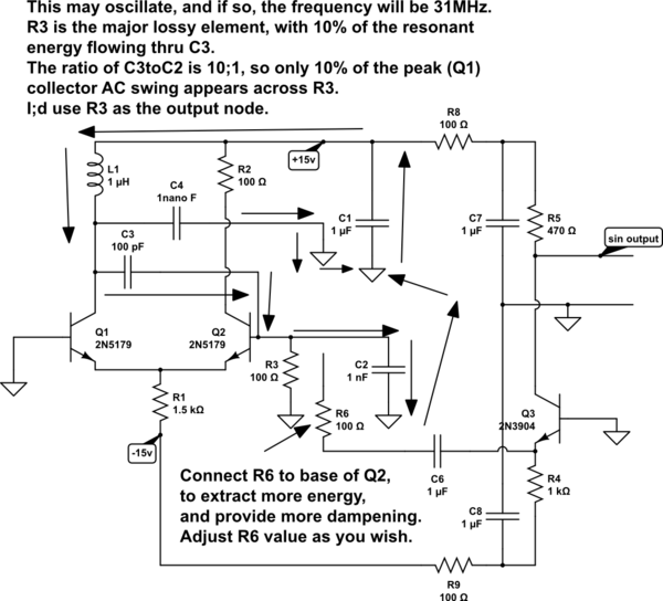
Some oscillators include a constant energy input to the amplifier (perhaps from a long-tailed-pair gain-pair (differential pair and current source)) and then use a load resistor (or power dissipator) that consumes the power and causes a predictable stable voltage peakpeak. The HP3326A Synthesizer had that type of VCO, where the pure sin circulating in the VCO was never distorted, thus there was no noise folding. [was HP3033]

Here is the circuit of the low-distortion oscillator; the arrows show the path (the closed path) of the circulating resonant energy.

schematic

simulate this circuit – Schematic created using CircuitLab

Notice R3 and R6 are also paths used by the circulating resonant energy; trash in the Ground paths used by those 2 resistors will upset the sinusoidal purity. And non-linearities, such as with R6 causing Q3 to rail (+15, or to GND), will upset the purity.

For highest purity, you may tie together the Ground ends of C1, C2 and C4 (and the Ground end of R3, and the base of Q1).

\$\endgroup\$

Your Answer

By clicking “Post Your Answer”, you agree to our terms of service and acknowledge you have read our privacy policy.

Not the answer you're looking for? Browse other questions tagged or ask your own question.