3
\$\begingroup\$

I wish to send data back-and-forth between a Master and one of a few dozen slaves within a mesh-network style arrangement.

Assume that all units are (identical) microcontrollers within my control, i.e., can be programmed. In the interest of maximizing data throughput to several hundred kb/s, I am considering SPI.

Are there any strategies or existing implementations to achieve such a topology while using only 1 or 2 pins/signal-lines in total, aside from MOSI, MISO, and CLOCK?

These 1 or 2 pins could be for a custom handshaking or slave-selection method, however what I don't want to do is spend one pin per EACH slave (or use multiplexing) due to some constraints, including the wiring arrangement and limited physical space on the hardware of each master and slave.

I see I2C raising its hand here, but would like to maintain the advantages of SPI (e.g., simplicity and much faster data transfer). I expect throughput would decrease somewhat in this kind of bus implementation especially if I use software-addressing/polling, but perhaps there is some smarter solution to not drag it down too much?

\$\endgroup\$
9
  • \$\begingroup\$ Depending on the devices, it is possible to daisy chain SPI. \$\endgroup\$ Commented Jan 27, 2019 at 15:45
  • \$\begingroup\$ @PeterSmith : Any comments about pros/cons? How much does daisy chaining impede transfer speed in a system with several dozen slaves? I've heard about it being used with ADCs, which is a positive sign. \$\endgroup\$
    – boardbite
    Commented Jan 27, 2019 at 15:48
  • \$\begingroup\$ It simply means that each transaction must run through all the daisy chained devices (so more data per transaction); some devices support it, others do not. If you list the devices we could give a view on that. \$\endgroup\$ Commented Jan 27, 2019 at 15:57
  • 1
    \$\begingroup\$ Daisy chaining would work but it means that full frames of SPI transmissions need to include slots for every possible device each time you want to target a communication. Not really a very robust solution if performance is important. \$\endgroup\$ Commented Jan 27, 2019 at 16:10
  • 1
    \$\begingroup\$ @FRob how's that relevant? I don't see anything in documents to address this question. \$\endgroup\$
    – domen
    Commented Jan 28, 2019 at 8:37

2 Answers 2

6
\$\begingroup\$

The solution here is to use SPI in an intelligent manner with embedded addressing. Each of the slave devices would be deployed with some type of device selection code using one of the following techniques:

  1. Have a small 6 or 8 position "dip switch" that can be set to the address in binary format.
  2. Use small rotary selector switches that encode a 4-bit value based upon the 0 -> 9 setting of the selector. Two of these can select addresses from 00 to 99.
  3. Have a setup mode in the slave where you interactively set the address and save it into non-volatile memory such as EEPROM or FLASH in the slave device.

When you devise your SPI protocol set it up so every slave device is connected in parallel so all receive the SPI_SEL, SCLK and MOSI signals. They are all also connected to MISO but keep their output driver tristated until they are addressed.

You utilize the SPI_SEL as a framing control so that all the slaves are alerted to the start of a SPI frame when the SPI_SEL signal goes to its active level. The first byte of the SPI data clocked out from the master on the MOSI is the address value for the desired slave device. All the slave devices compare the address received against their specified address. Upon a match the addressed slave will enable its output onto the MISO line and remain actively connected until the SPI_SEL goes to its inactive level.

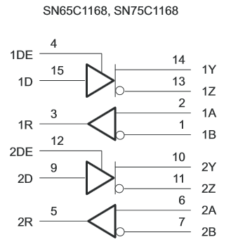
This scheme adds very little overhead to the overall SPI bandwidth and makes the connection wiring easy to implement. Since it seems that each of the many slaves are all on separate boards it may become necessary to buffer the interface lines so that the fanout to all the slaves has enough drive to properly operate the interface. One way to do this if longer distances are possible is to deploy the usage of differential drivers and receivers on the signal lines such as in a common chip like as an RS422 type transceiver. A chip that would work well to create the differential interface would be the TI SN75C1168. Two of these at each slave would provide the receivers for SPI_SEL, SCLK and MOSI. The one of the drivers can support the MISO signal with its tri-state control. The same two chips can be used at the master side to provide for the needed three drivers and one receiver on that end of your differential SPI bus.

enter image description here

(Picture Source: http://www.ti.com/lit/ds/symlink/sn75c1168.pdf)

\$\endgroup\$
12
  • \$\begingroup\$ "Upon a match the addressed slave will enable its output onto the MISO line and remain actively connected until the SPI_SEL goes to its inactive level" --> Elegant solution, especially this part, thank you. \$\endgroup\$
    – boardbite
    Commented Jan 27, 2019 at 18:10
  • \$\begingroup\$ About your suggested setup: I also wish to put the Master in a low-power/sleep mode when not sending data. To allow a Slave that has new information to send to the sleeping Master, I'm thinking I could set the SPI_SEL line as an input (hardware interrupt-capable) on the Master prior to sleeping. That way, the Slave which wishes to send new data can assert the SPI_SEL line high, waking up the Master. The Master in turn clocks out an SPI transfer to which the Slave responds with the new data. Thoughts? \$\endgroup\$
    – boardbite
    Commented Jan 27, 2019 at 18:15
  • \$\begingroup\$ @boardbite - It may be possible to make that work with the SPI_SEL but I think it adds more complication than it is worth. If it were me I would poll the slaves periodically to see if they have data/events to report. Alternatively you could just add an additional wire that is from all the slaves back to the master that is an interrupt/wake signal. You could encounter some difficulty with trying to wire-OR the interrupt/wake line from all the slaves. You would have to use the driver enable at the slaves to enable the interrupt/wake signal and keep the input to the driver (continued) \$\endgroup\$ Commented Jan 27, 2019 at 18:32
  • 1
    \$\begingroup\$ To deal with interrupts, you can have an interrupt-poll mode by reserving at least one address for it and making the MISO line open-drain (or its differential equivalent). Then any interrupting slave just needs to set its corresponding bit to zero in response to the polling. The simplest implementation would require 32 bytes for 256 slaves, but by using separate interrupt query addresses, this can be greatly reduced. \$\endgroup\$ Commented Jan 28, 2019 at 4:28
  • 1
    \$\begingroup\$ For a total wiring distance of 30cm, and particularly if all devices share a decent DC grounding system, you probably would not see much benefit to the use of the differential drivers and receivers. For fanout the Master will need a decent driver as it has to drive the 20+ loads of all devices on the SPI_SEL, SCLK and MOSI lines. That loading is mostly going to be capacitive in nature and your desired high data rates will require needing to be able to swing the lines up and down with as fast of rise time required for your data rate. Ringing may become a problem on unterminated (continued) \$\endgroup\$ Commented Jan 29, 2019 at 12:19
1
\$\begingroup\$

Two methods come to mind.

  1. Use a digital I/O expander to create additional slave-select lines. Control the expander through that same SPI bus. Slave-select the expander itself using that single SPI slave-slect line that's available from the microcontroller.
    Do a separate SPI transaction to set the I/O expander, before talking to the "payload" device.

  2. If you have two lines (in addition to MISO, MOSI, SCLK), you can connect them to a 2-to-4 decoder. That would allow you to select 3x slave devices (fourth one of the decoder outputs is for selecting none of the "payload" devices).

\$\endgroup\$

Your Answer

By clicking “Post Your Answer”, you agree to our terms of service and acknowledge you have read our privacy policy.

Not the answer you're looking for? Browse other questions tagged or ask your own question.