1
\$\begingroup\$

I am looking for an LED driver circuit that would illuminate when a voltage is at zero, and which would gradually shut off as a voltage rises to 3.3v, with a (somewhat) direct relationship between brightness and voltage level.

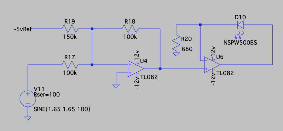
I have already designed this circuit using an inverting op amp to invert and offset the control voltage signal with a negative reference, and then a second op amp to drive the LED using the feedback path.

I am hoping that someone might know of a simpler design, that would be lower cost and fewer parts. As it stands, this will cost me about $0.30 and uses 5 parts (not counting the LED itself). I need 16 of these in a single circuit, and I was hoping to be able to reduce the cost to below $2 total, ideally below $1

Inverting LED Driver Circuit1

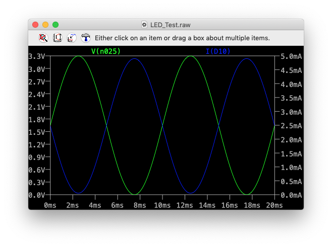
And here is the signal analysis, where the Green line is the 0-3v3 control signal, and the Blue line is the current used by the LED itself.

enter image description here

UPDATE 1:

One additional constraint I forgot to mention is the control input must be high impedance, as that signal will be needed for other purposes as well

\$\endgroup\$
2
  • \$\begingroup\$ You should have a diode across the LED to prevent exceeding the absolute maximum 5V reverse voltage. \$\endgroup\$ Commented Mar 27, 2019 at 23:22
  • \$\begingroup\$ In a non controlled situation, yes I would agree with you, however other parts of the circuit are controlling the CV signal, so I can be sure it will never exceed the reverse voltage limit. \$\endgroup\$
    – cosmikwolf
    Commented Mar 28, 2019 at 0:24

4 Answers 4

4
\$\begingroup\$

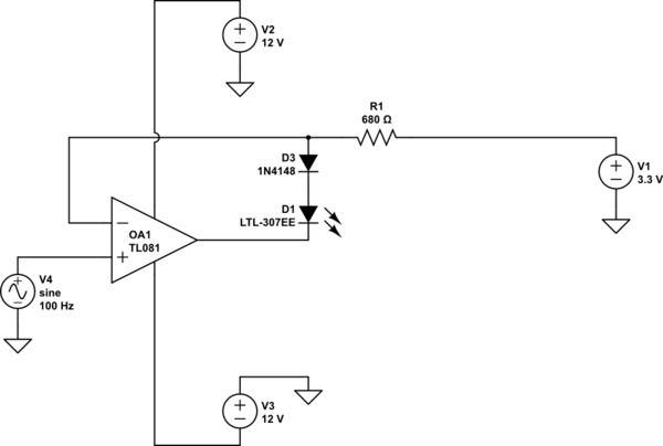
schematic

simulate this circuit – Schematic created using CircuitLab

The 3.3V comes from a regulator for the LEDs (one required). If you reduce the positive rail on the op-amps to +8V or so you could use quad LM324 op-amps and avoid the diodes, so total 8 parts (4 LM324 + 4 resistor networks) + 2 regulators if you use x4 resistor networks. Plus the LEDs.

That's about $0.03 USD per driver and 0.5 parts per driver (not counting regulators or LEDs) in 250 unit quantity- Digikey list price.

Note that inputs are high impedance and can withstand input voltage from a bit below the negative rail up to 32V.

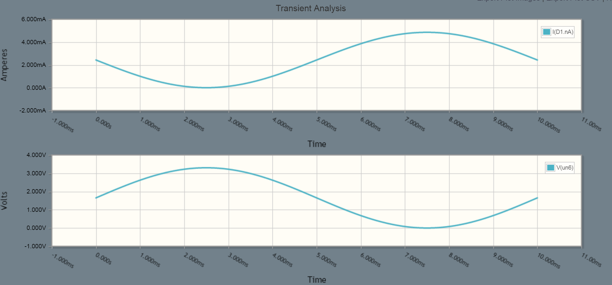
enter image description here

\$\endgroup\$
7
  • \$\begingroup\$ This solution looks great! I am curious, why is the 1N4148 diode needed when using a TL08X? It seems to work fine in spice without it. I cannot reduce the rails to 8v, they are supplied as ±12v \$\endgroup\$
    – cosmikwolf
    Commented Mar 28, 2019 at 0:19
  • \$\begingroup\$ But also, LM324 datasheet seems to say that it is capable of ±16v supplies... \$\endgroup\$
    – cosmikwolf
    Commented Mar 28, 2019 at 0:31
  • \$\begingroup\$ The LED is rated for absolute maximum 5V reverse voltage. With your input at 3.3V and your reference at 3.3V the slightest offset voltage (in the wrong direction) will rail the op-amp at the opposite rail and you'll get excessive negative volts across the LED. You will see this in your simulation if you model offset voltage. The 8V supply is solely to save the 16 diodes. (eg just a single LM7808). The current draw is very low (about 16mA) so no heatsink required. \$\endgroup\$ Commented Mar 28, 2019 at 0:45
  • \$\begingroup\$ Ah, makes sense. Thank you for your explanation! This is definitely the best option I have considered so far. \$\endgroup\$
    – cosmikwolf
    Commented Mar 28, 2019 at 1:14
  • 1
    \$\begingroup\$ Good point. I didn't think of that. \$\endgroup\$
    – EinarA
    Commented Mar 30, 2019 at 3:44
1
\$\begingroup\$

schematic

simulate this circuit – Schematic created using CircuitLab

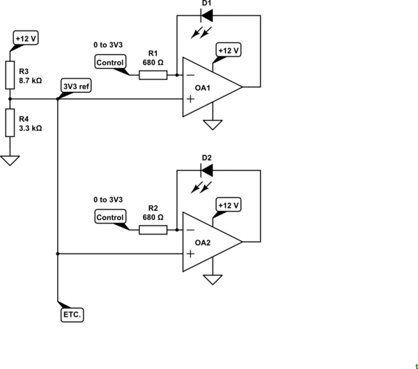
Figure 1. Voltage controlled LED current.

How it works:

  • R3 and R4 with OA2 provide a common 3.3 V reference for each channel.
  • With Control at 3.3 V the op-amp will be stabilise with the inverting input at 3.3 V, no current through R1 and, therefore, zero current through the LED.
  • With Control at 0 V the op-amp will again stabilise with the inverting input at 3.3 V. This time there will be 4.8 mA through R1 and, therefore, through D1.

I have not considered what will happen at power-up and whether any protection is required to prevent high-current spikes or through the LEDs. Reverse voltage on the LEDs is limited by grounding the op-amp negative supply rather than using -12 V as in your design.

The minimum output voltage required of the op-amps is 3.3 V so rail to rail op-amps are not required.

\$\endgroup\$
1
  • \$\begingroup\$ Ah, I so want this to work! Please see my update 1. This is such a simple solution, but unfortunately the control input is low impedance, and would require an additional op amp to buffer the signal for each channel. \$\endgroup\$
    – cosmikwolf
    Commented Mar 28, 2019 at 0:13
0
\$\begingroup\$

A very crude circuit would be a PNP darlington with collector to ground, Vc to the base, and the LED and it's resistor between the emitter and a reference voltage. This would be very nonlinear at maximum Vc but this could be improved with a bias resistor from the emitter to V+. Two or three cheap parts.

\$\endgroup\$
0
\$\begingroup\$

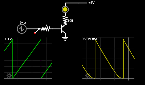
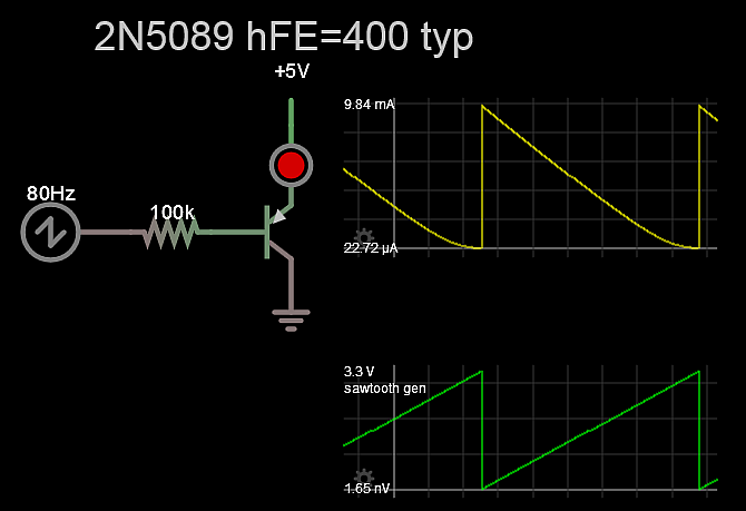
This works for Red Yellow LEDs that are typically Vf=2.0 to 2.1V with a very dim or off threshold at 1.7V such that 3.3+1.7=5.0V

It doesn't get much simpler than this.

enter image description here

Rev A enter image description here

\$\endgroup\$
3
  • \$\begingroup\$ While this is functional, it is not ideal. The input impedance in your example is 1k, and I need at least a 100k input impedance (see update 1). I was able to get it to work with a 100k input impedance, but I only get about 3.2mA of current, and I don' think it will satisfy my brightness needs. \$\endgroup\$
    – cosmikwolf
    Commented Mar 28, 2019 at 17:47
  • \$\begingroup\$ I have 5mm Yellow Leds with >2,000 mcd at 3mA, very bright, and blinding at 20mA \$\endgroup\$
    – D.A.S.
    Commented Mar 28, 2019 at 17:49
  • \$\begingroup\$ The first circuit is the same as the one I suggested but I specified a transistor with sufficient beta to give you the input desired. Just because some one has more points doesn't mean they have better ideas. \$\endgroup\$
    – EinarA
    Commented Mar 30, 2019 at 3:22

Your Answer

By clicking “Post Your Answer”, you agree to our terms of service and acknowledge you have read our privacy policy.

Not the answer you're looking for? Browse other questions tagged or ask your own question.