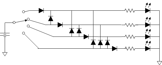
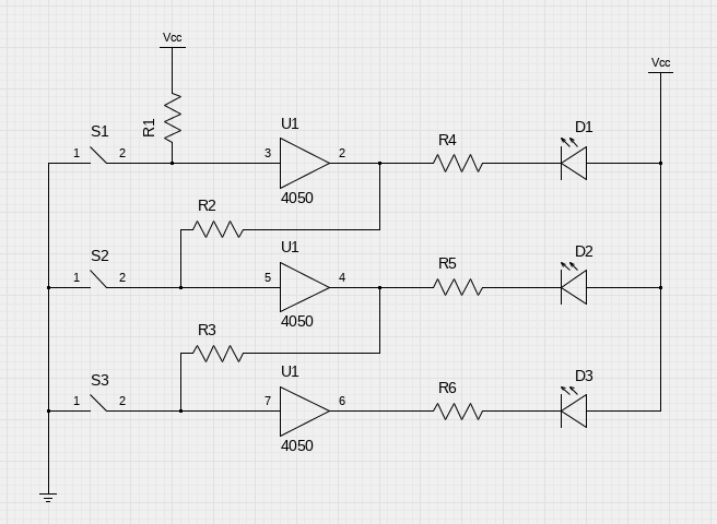
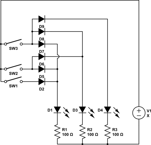
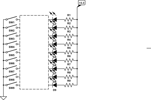
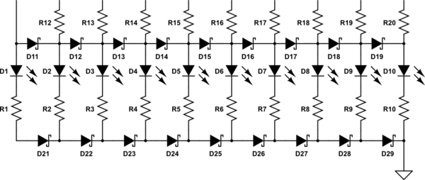
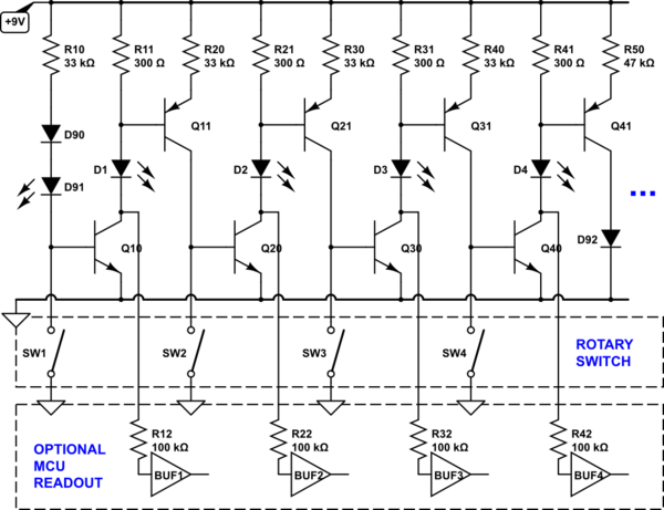
Oldfart and Mattman944 give very similar answers involving complex diode networks. If brightness variation is acceptable a simple diode ladder is sufficient. Red LED's typically have 2V voltage drop and diodes typically have 0.6V voltage drop, so the combined effect of the diode voltage drops in a ladder is can be significant.
With a 9V battery and the switch in position 9, the current limiting resistor for LED 9 will see 9-2=7V and the current limiting resistor for LED 1 will see 9-2-(0.6*8)=2.2V, which will lead to a more than threefold difference in current through the LEDs if the current limiting resistors are of the same value.
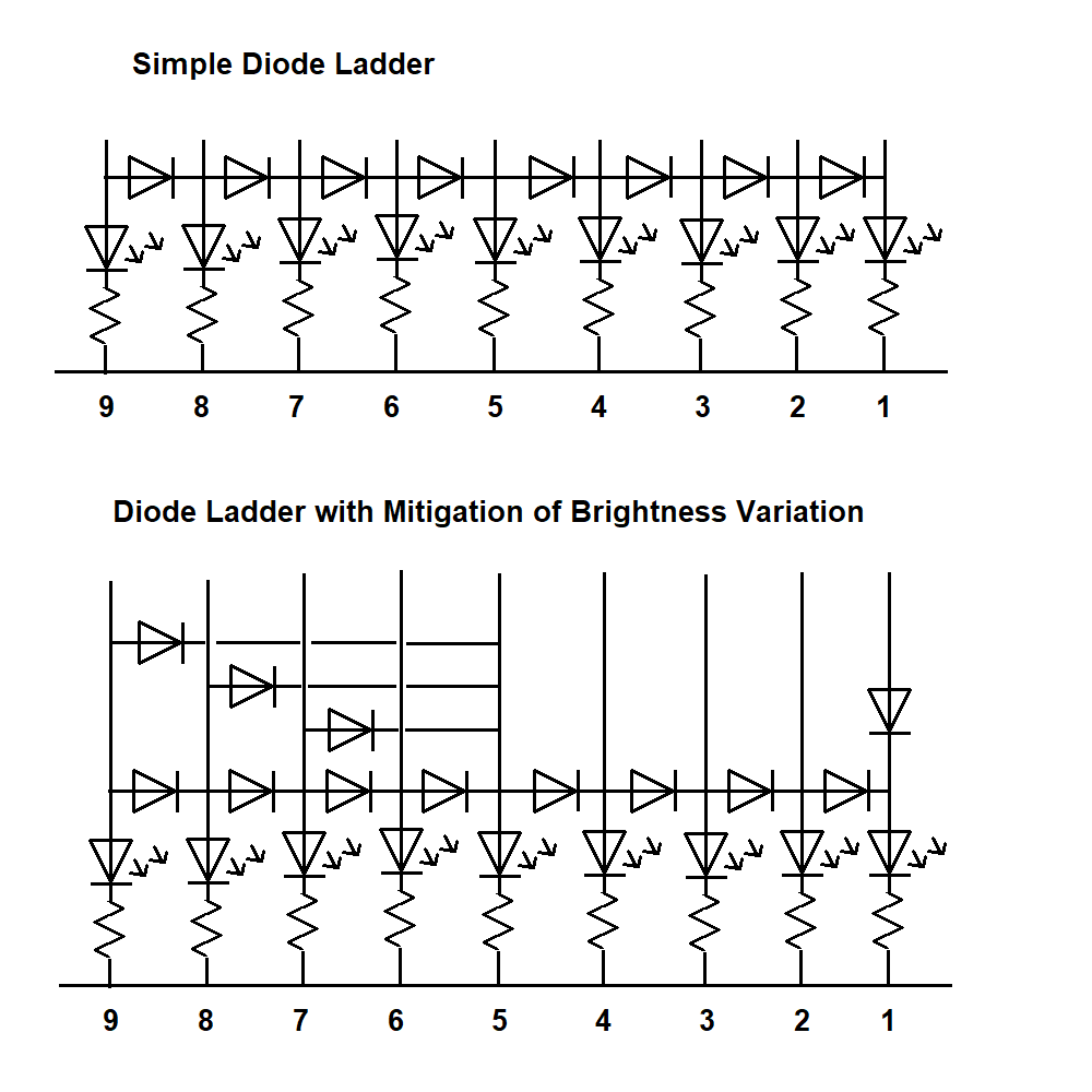
If you insist on equal brightness it would be necessary to include all the diodes recommended by Oldfart and Mattman944, but with only a few extra diodes you can mitigate the variation in brightness to hopefully imperceptible levels. By adding three more diodes at the left as in the drawing above, we ensure that with the switch in position 9, LED 5 sees the same voltage as LED 8. The actual voltages across the current limiting resistors are as below. Note that an additional diode between LED's 5 and 2 (not considered in the table below) would improve the circuit further.
LED  Voltage across current limiting resistor
9             7
8    7-0.6   =6.4
7    7-0.6*2 =5.8
6    7-0.6*3 =5.2
5    7-0.6   =6.4
4    7-0.6*2 =5.8
3    7-0.6*3 =5.2
2    7-0.6*4 =4.6
1    7-0.6*5 =4
Another way of balancing the brightnesses is to install diodes in the lines to some LED's to deliberately increase the voltage drop. In the drawing above an additional diode is inserted into the line from switch contact 1 to LED 1, so that LED 1 sees the same voltage regardless of whether the switch is in position 1 or 2. The current limiting resistor for LED 1 can then be a smaller value than the others in order to balance the brightness of this LED with the others.
These are just ideas - for this type of project the best balance of even brightness versus complexity may be best found by experimentation.


