1
\$\begingroup\$

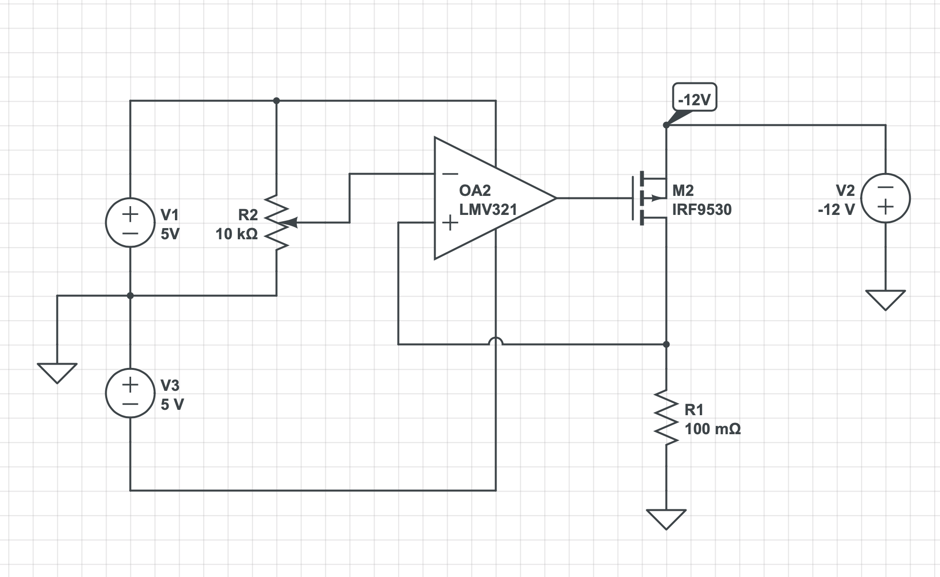
I am making a MOSFET based electronic load to test my PSU rails. Below is a simplified version of my circuit with V2 as the PSU that is being tested. I want to be able to test negative voltage rails too, which must share a common ground with the supply voltage (V1).

Is there some way to simply modify this type of design to allow for negative voltages to be loaded?

thanks!
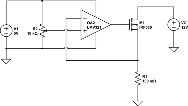
schematic

simulate this circuit – Schematic created using CircuitLab

NEW DESIGN

\$\endgroup\$
11
  • 1
    \$\begingroup\$ Do you want one circuit to handle both positive and negative voltages, or do you want to design a circuit that will work for negative voltages (only)? \$\endgroup\$
    – JimmyB
    Commented Jun 17, 2019 at 13:47
  • \$\begingroup\$ It would be great if it could handle both positive and negative voltages, but if that makes it much more complicated then Negative voltages only is fine. Ideally though, the Negative voltage circuit would not be so different from the positive version. that way I could make a universal PCB where I just have to change a few components to make it a negative version. Thanks! \$\endgroup\$
    – Benjamin
    Commented Jun 17, 2019 at 13:55
  • \$\begingroup\$ Your (read: every) op amp will have a hard time dealing with inputs below its own negative supply rail (read: it won't work). So, among other changes, you'll have to either modify the amp's supply, or find a way to transform the sensed voltage to an appropriate value. \$\endgroup\$
    – JimmyB
    Commented Jun 17, 2019 at 14:03
  • \$\begingroup\$ How much voltage drop across R1 is acceptable? I.e., what's the maximum current you want to measure at what minumum V2? \$\endgroup\$
    – JimmyB
    Commented Jun 17, 2019 at 14:04
  • \$\begingroup\$ I can operate this from a +/-12V supply if that helps. I was planning on using a linear regulator to derive the 5V from 12V, because I thought that would help with stability. The rails I want to measure are also +12V or -12V at up to 4.5A (if possible). so I guess the maximum voltage across R1 is 0.45V. I chose 0.1 Ohms because it seems like I would have to dissipate less heat in the resistor \$\endgroup\$
    – Benjamin
    Commented Jun 17, 2019 at 14:27

0

Your Answer

By clicking “Post Your Answer”, you agree to our terms of service and acknowledge you have read our privacy policy.