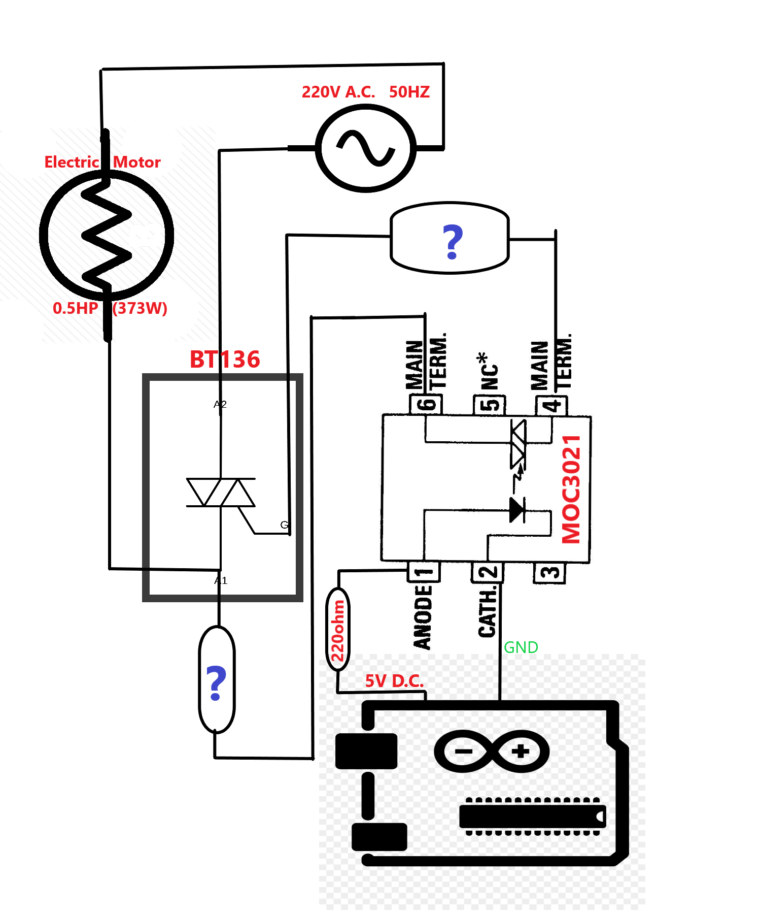
I have made the following circuit to control my water pump with Arduino(UNO R3). I have tried many resistors (calculated myself) to limit current in the optocoupler and triac, but failed to carry the load for a long time. At one time either resistor get burned or triac gets too hot. Kindly suggest what resistance I should use in the resistors with '?'. Any other suggestions are also welcome.
-
\$\begingroup\$ The triac needs to dissipate about 3W, do you have a heatsink? \$\endgroup\$– Mattman944Commented Jun 24, 2019 at 16:09
2 Answers
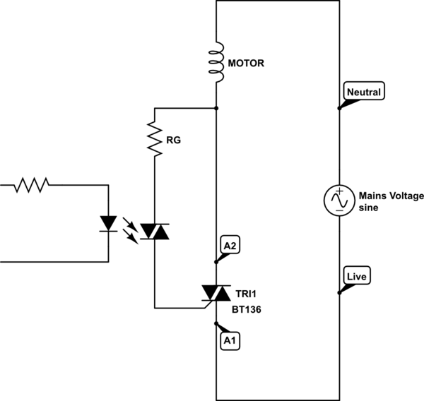
Your circuit's incorrect, try this.

simulate this circuit – Schematic created using CircuitLab
For BT136 to switch on you must make a voltage difference (positive or negative) between the gate and A1 which happens, with this circuit, after mains zero crossing.
The triac triggers in quadrants I and III thereby avoiding quadrant IV triggering.
RG is calculated by considering the triac's Vgt and Igt parameters. Assume a minimum mains voltage at which you want the triac to switch on, say 20V.
Then RG = (20 - Vgt)/Igt.
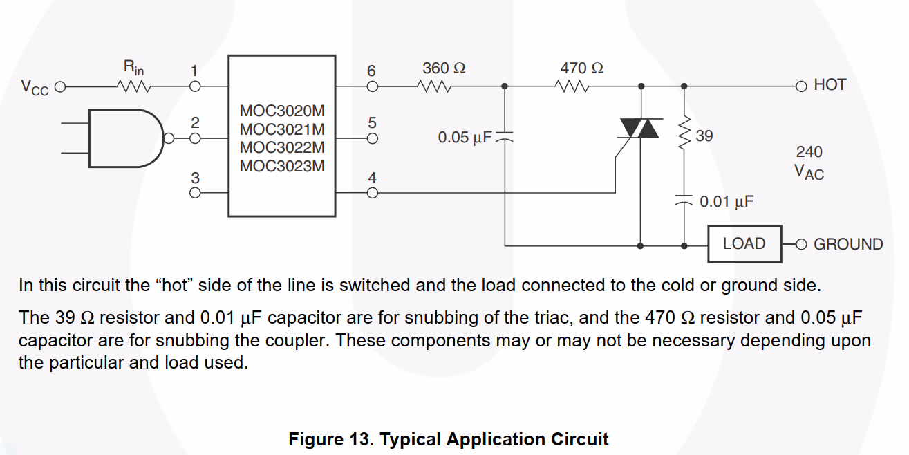
This circuit could be improved with the addition of a snubber network across the triac to guard against dv/dt turn on and ensure that the triac commutates correctly (switches off at mains zero crossing). - This is because the load is inductive.
EDIT
If too low a value of mains turn-on voltage is chosen then RG will be too small and the peak allowable gate current (IGM) data sheet specification will be exceeded.
To calculate the minimum value of RG assume the opto triac turns on when the mains voltage is at its peak. MOC3021 is a random phase (non-zero crossing) triac driver.
RG(min) = (Vpk - Vgt)/IGM = ((230V * sqrt(2)) - 1.5V)/2A = 162R (in the UK).
Allow a safety margin, let RG(min) = 200R.
Now it's possible to calculate the minimum mains turn-on voltage using this value of RG.
If Vgt = 1.5V and Igt = 35mA then...
Minimum mains turn-on voltage = (35mA * 200R) + 1.5V = 8.5V
-
\$\begingroup\$ Mains voltage =220V, Vgt=1.5V and Igt=100mA. Thus RG=2185 ohm. Should I go for it? Thanks for your suggestion. \$\endgroup\$ Commented Jun 25, 2019 at 5:05
-
\$\begingroup\$ The voltage in my equation (20V) is the voltage that the mains voltage waveform rises to across the triac when the triac switches on. You have used the mains rms value which is not correct for this calculation. If you follow my edit I have suggested RG = 200R, with the mains rising to 8.5V across the triac when it switches on. This results in nearly the full cycle of the mains being developed across the motor giving almost the full power of the mains voltage. \$\endgroup\$– user173271Commented Jun 25, 2019 at 9:22
-
\$\begingroup\$ …. also you have used the Igt specification for fourth quadrant triggering which is much higher than the first and third quadrant triggering which this circuit utilises. \$\endgroup\$– user173271Commented Jun 25, 2019 at 9:30
-
\$\begingroup\$ I've edited my circuit diagram above by swapping over the Neutral and Live connections with each other. This is because the switch (the triac) should be in the Live circuit which results in the load (motor) being at Neutral voltage (close to ground) when the switch is open (triac switched off). This is therefore a safer configuration. \$\endgroup\$– user173271Commented Jun 26, 2019 at 14:19
-
\$\begingroup\$ Hey James, thank you so much. My circuit is working fine now. I have used 1.3K ohm (three 3.9K ohm in parallel). To overcome heating, I have used a 2cm long aluminium heat sink with fins and a cooling fan. \$\endgroup\$ Commented Jun 27, 2019 at 16:10

