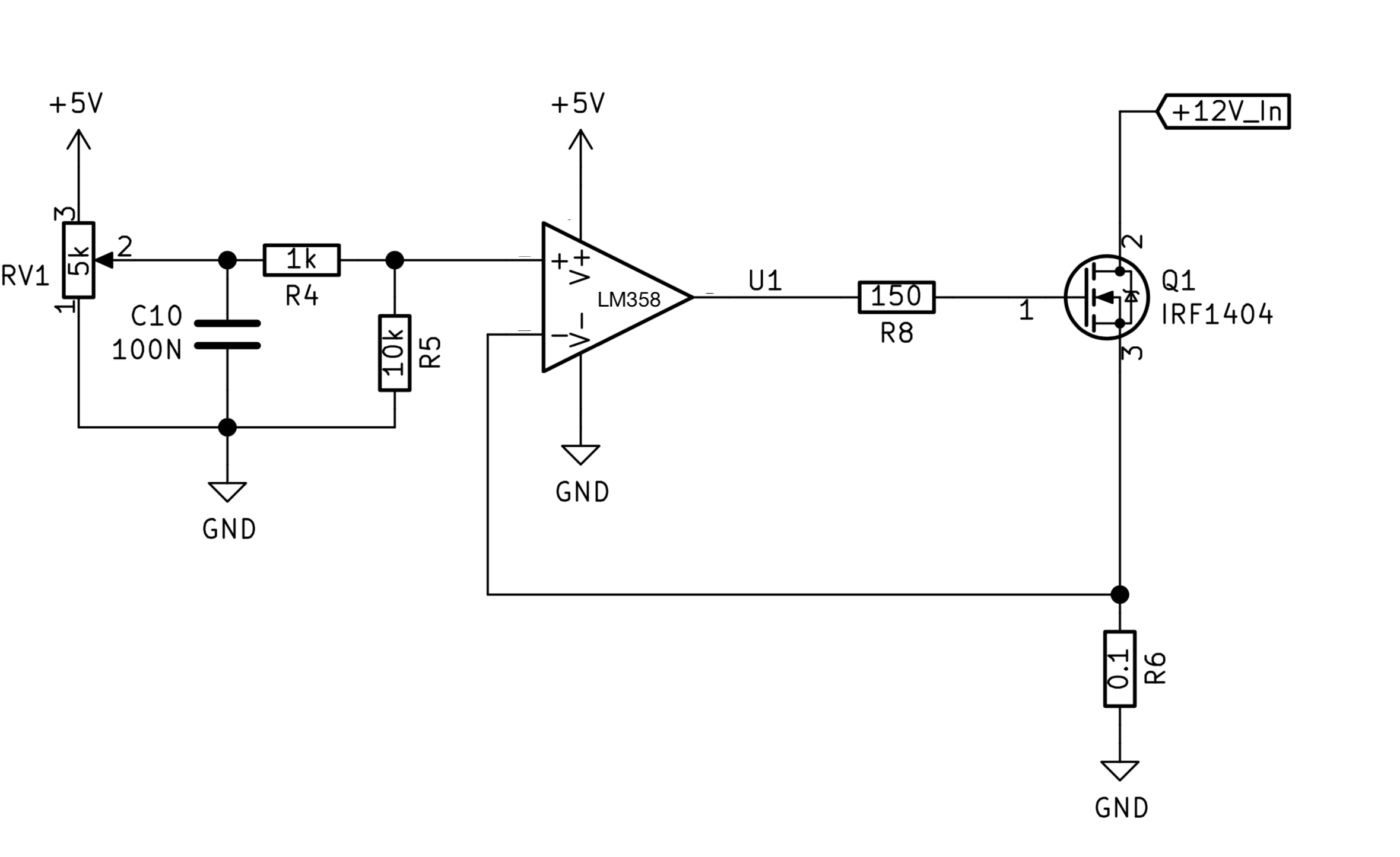
I am trying to make an adjustable dummy load to test a 12V supply, I’m having trouble with the op-amp feedback circuit. Attached is a simplified schematic. I have tried lots of things and stripped it down to this.
Basically when +In of the op-amp is 0V, the output of the op-amp goes to the negative rail. In this case the negative rail is 0V, but when powered with a +/-5V supply, the output goes to -5V. In this state the MOSFET is fully off
When I add just a tiny bit of positive voltage to the +In of the op-amp, The output shoots straight into positive saturation and goes as close to the positive rail as it can get (about 3.7V) and stays there no matter how much voltage I give to the +In. At this point the MOSFET is on, and allows approximately 250mA to flow through though.
Any ideas on what this could be?
Things I have tried: - removing R6 and Q1 and connecting R8 to -In. At this stage I get a normal voltage follower. - Changing the FET - Raising the resistance of R6
On a side note, there is one way that I can get the load to be variable, and that is by removing the heat sink from the MOSFET. I have only done this for short periods of time.


