1
\$\begingroup\$

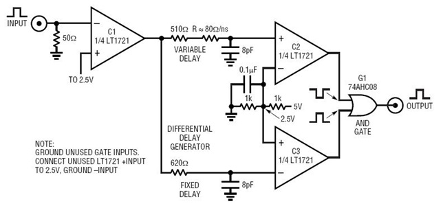
I've designed a circuit depending mostly on this LT1721 pulse generator, that's been thought up by the nice people at Analog:

enter image description here

https://www.analog.com/en/design-center/reference-designs/circuit-collections/lt1721-pulse-generator-has-0ns-to-10ns-width-520ps-transitions.html#cc-overview

My goal is to generate 5 ns pulses to feed into the gate of a FET.

The pulse generator works because C2 is initially on, wheras C3 is initially off. Then as the input pulse passes, the 8 pF capacitors are discharged into C1. If the C3 capacitor discharges before the C2 capacitor, there is a brief window of time when both C2 and C3 are on, and the and-gate sends out my pulse.

Of course the larger my C2 resistor, the longer the delay and the longer my pulse will be. I'm trying to settle on resistors such that my pulse will be 5 ns!

Now this article tells me that I need to choose my C2 resistor as 510 Ohms, plus 80 Ohms for each nanosecond delay I want, wheras I need to choose my C3 resistor as 620 Ohms. So this would give me resistor values of 910 and 620 Ohms.

But when calculating the voltage at the C2 and C3 input pins, these resistor values give me a time delay of only about 2.5 ns! In fact, the 5ns pulse I want corresponds to 510 and 1500 Ohm resistor values. See these calculations: https://www.desmos.com/calculator/ca5ykt03je LTSpice agrees with me too, if that's worth anything.


Now my questions are twofold:

  • The people at Analog are smart. Why do they recommend these resistor values when they are so far from a conventional calculation? Is there some effect I'm not seeing? Some extra capacitance somewhere? For a 1 ns delay, the C2 resistor is lower than the C3 resistor: how could that even work in the first place?

  • I'm inclined to go with a 510 Ohm and a 1510 Ohm resistor. Would that be okay? The top line would start sinking about 4 mA into C1, the bottom line 10 mA. The datasheet tells me that the output current can sink 20 mA, so I should be fine making these "modifications"?

\$\endgroup\$
11
  • \$\begingroup\$ Have you considered their output voltage vs current curves and the output impedance on your calculations? (No, I've not attempted to read or replicate your results, yet. I'm just curious.) \$\endgroup\$
    – jonk
    Commented Nov 3, 2019 at 19:27
  • \$\begingroup\$ What capacitance are the comparator input pins? Is there a slight mismatch between the input capacitances? Theer might be enough to explain the R values. \$\endgroup\$
    – user16324
    Commented Nov 3, 2019 at 20:08
  • \$\begingroup\$ @BrianDrummond that was my initial guess as well, but the datasheet only mentions an input capacitance of 2 pF in two places. That doesn't shift the pulse width by more than ~500 ps, and is still symmetrical, as far as the datasheet's concerned. \$\endgroup\$ Commented Nov 3, 2019 at 20:44
  • \$\begingroup\$ @jonk Thanks for the interesting suggestion. I'm not exactly sure how I'd modify my calculation to incorporate those. I hadn't thought of the compararator output having a IV-curve, and now I see it has. But shouldn't that offset have a symmetric effect, since the it is caused by the sum of the two sinking currents? And the output impedance should have a symmetric effect too, right? \$\endgroup\$ Commented Nov 3, 2019 at 20:51
  • \$\begingroup\$ @Heatherfield I'm only thinking about the timing. Symmetry about a "point" (where ever that point may be) doesn't discuss its slope. The hysteresis may be achieved slower with a gentler slope and more quickly with a faster slope. So the time itself does depend on more than an imagined "symmetric effect." (And I'm not sure I'm convinced of the symmetry, either, given a pair of curves I just looked at for a moment.) I think the point here is that the authors probably have access to the IC designer(s) and more data than you do. Is there a demo board you can buy? Can you just try and see? \$\endgroup\$
    – jonk
    Commented Nov 3, 2019 at 20:55

1 Answer 1

1
\$\begingroup\$

I will offer an answer based on a general knowledge of comparators rather than a knowledge of the LT1721. It is normal for comparators to have a different propogation delay for the high to low transition than the low to high transition. This would explain the circuit behavior but I have not looked at the data sheet.

\$\endgroup\$
1
  • \$\begingroup\$ Thanks for the answer. The datasheet tells me to indeed expect a 300 ps difference. That does not account for everything, but I do suppose it is a substantial part of the answer. \$\endgroup\$ Commented Nov 3, 2019 at 21:59

Your Answer

By clicking “Post Your Answer”, you agree to our terms of service and acknowledge you have read our privacy policy.

Not the answer you're looking for? Browse other questions tagged or ask your own question.