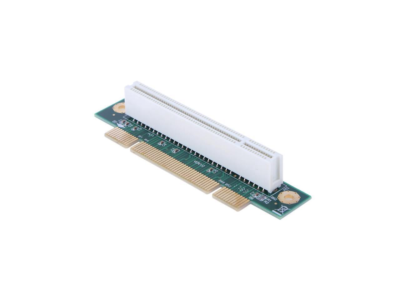
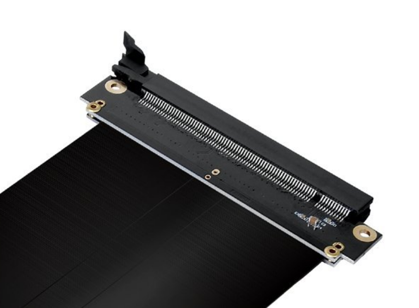
I'm looking to make a custom PCI Express right angle adapter because the ones on the market don't work with my space constraints. Now, because it's basically an extension cable, I'd imagine it should be just straight traces running from the female connector to the male board edge. However, the adapter boards and even extension cables appear to have resistors or capacitors AND don't appear to have straight traces. Why is that?
1 Answer
The components are necessary for noise filtering and decoupling. Keeping ground return loops as close as possible where they come from will stop stray currents and return signals having to travel longer distances than necessary.
Furthermore, when you are running at multi-GHz, signals stop behaving like current in a wire, instead acting as radio waves being guided down a wire. When you have a differential pair, it is necessary to ensure that both sides of the pair (the P and N) travel exactly the same distance, otherwise the will end up out of phase with each other.
The PCIe connector has its pins space apart from each other, meaning without the little bump in one side of the pair will travel further than the other. The bump brings them back in sync. Normally for extremely high speed routing, this should be done as a series of small wiggles, not one single big lump. You can get away with this sort of lump for PCIe Gen 1 and maybe Gen 2, but for the 4GHz Gen 3 it will cause all sorts of signal integrity issues.


