I have tried search via google images, but it's not good at recognizing line drawings
1 Answer
\$\begingroup\$
\$\endgroup\$
1
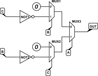
Drawn as logic instead of transistors, it looks like this:

simulate this circuit – Schematic created using CircuitLab
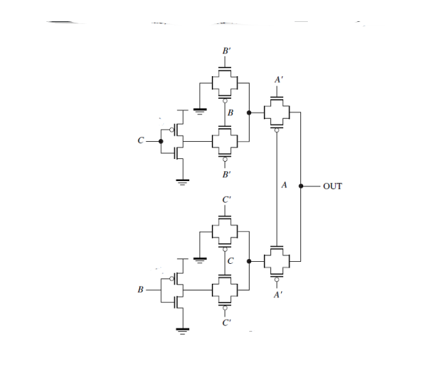
The bottom branch is A & !B & C, the top branch is !A & B & !C, so the final expression is
$$OUT = A \overline{B} C + \overline{A} B \overline{C}$$
It isn't clear why this was implemented as multiplexers rather than a more conventional SOP circuit.
-
\$\begingroup\$ I didn't make the circuit. Just curious about it. \$\endgroup\$– MelvinCommented Nov 21, 2019 at 2:12

