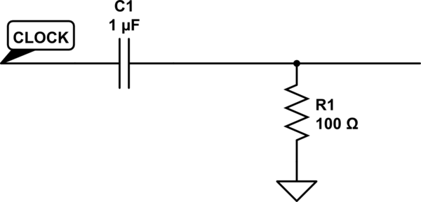
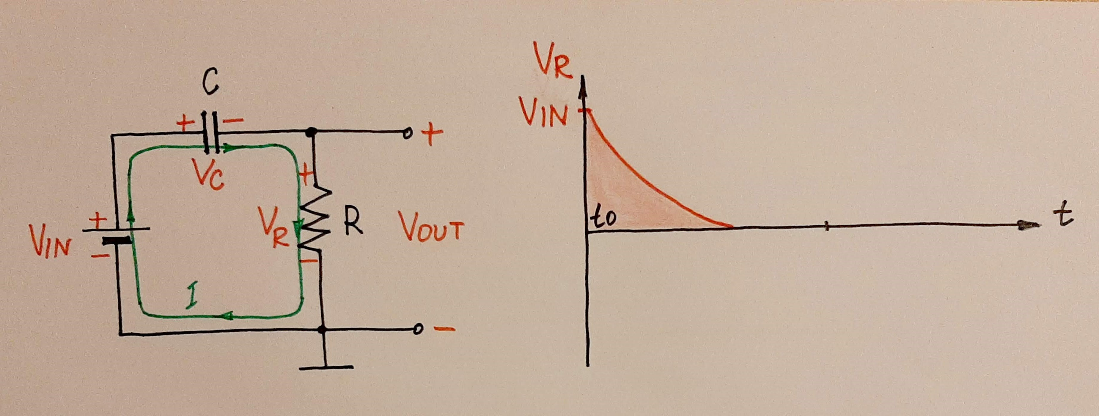
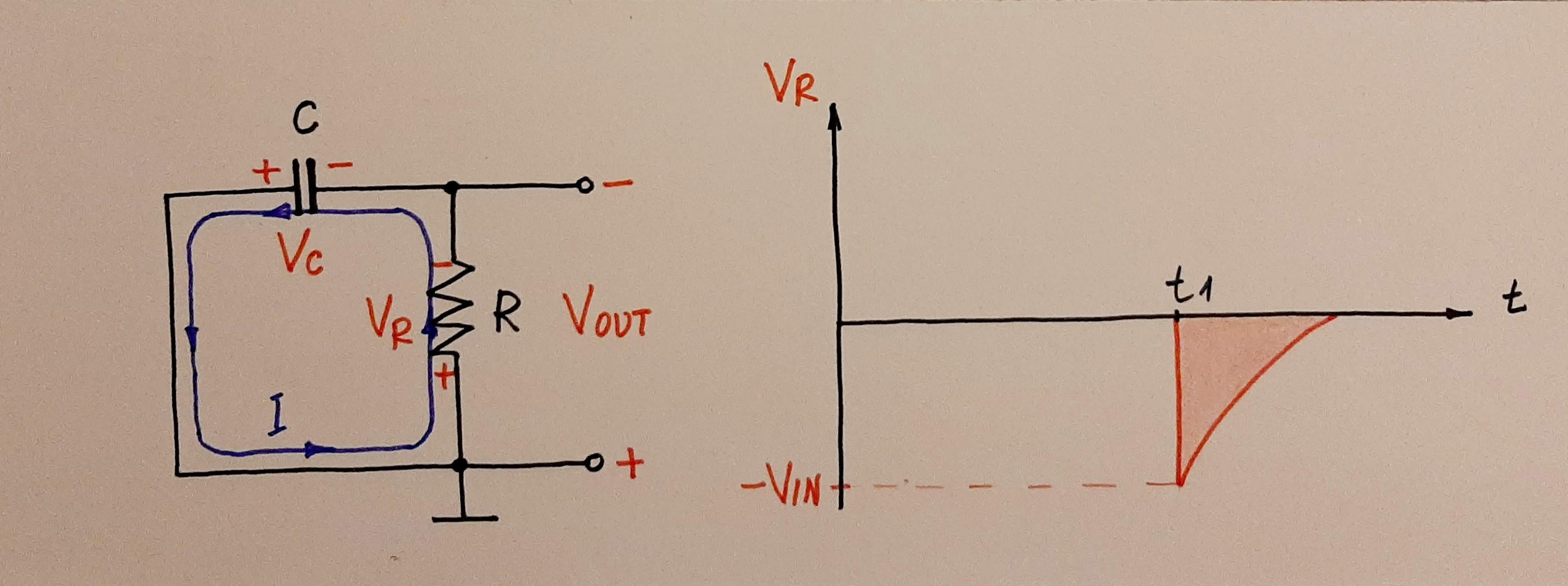
As others have mentioned in the comments, the circuit you are looking at is called a differentiator.
The differentiator makes use of the properties of a capacitor to mimic mathematic differentiation.
Capacitors are (more or less) "transparent" to changes in voltage, but "opaque" to constant voltages.
That is, a changing voltage will cause current to flow through the capacitor.
In a square wave, the voltage only changes on the rising or falling edge. In between, the voltage is either constant high or constant low. On the edges, current flows through the capacitor because the voltage changes. In between, no current flows because the voltage is constant.
It is as you suspected: the capacitor sometimes acts like an open circuit, and sometimes like a low value resistor.
There is in fact a mathematical expression for the resistance (or, rather, impedance) of a capacitor for a given frequency:
$$Z = \frac{1}{2 \times \pi \times f \times C}$$
Where:
- \$f\$ is the frequency in hertz
- \$C\$ is the capacitance in farads.
- \$Z\$ is the impedance in ohms.
A differentiator is also a high pass filter.
This circuit from the Wikipedia "High pass filter" page is the same as your differentiator:
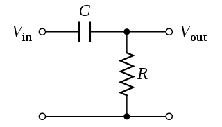
Since any signal can be viewed as a sum of frequencies of many frequencies, you can view a differentiator as a high pass filter that removes the lower frequencies (and DC) from your signal. It passes only the high frequencies, and the sum of the high frequencies is a spike.
The wikipedia page on square waves has a nifty animation of building a square wave from many sine waves:
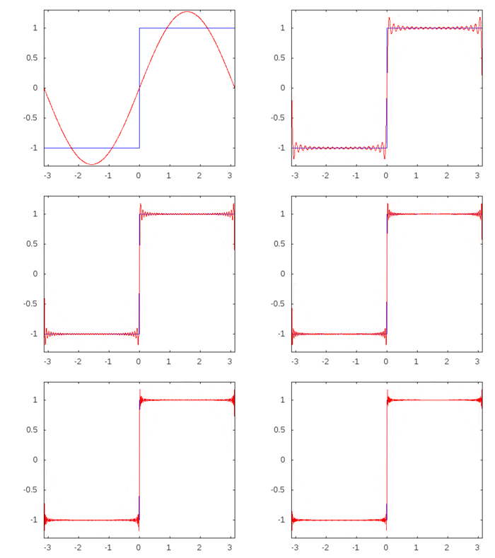
If you imagine leaving out the low frequency parts (the wider sine wave at the beginning) then you can see how a high pass filter can result in the spikes that a differentiator makes out of a square edged clock.
Note that the differentiator can only make spikes from a square wave.
If you need short spikes from a signal that looks like a sine wave, then you must first make a square wave out of it and then run it through a differentiator.
