3
\$\begingroup\$

An automotive-style alternator works from 750 RPM to e.g. 7000 RPM, a range of nearly 10:1.

In terms of output voltage, I know they target a fixed output voltage, but I believe it wouldn't be too hard to change the voltage regulator so that it targets 16V for example. 24V is probably also possible, but that's where I'm starting to guess, and this question arises.

To what extent can an alternator's parameters be varied, especially in terms of output voltage?

EDIT: I'm also concerned with practicality. As in, "it will work, but the alternator efficiency will be abysmal at the extremes of the RPM range" - then it's not really working.

Background (for the curious)

I'm asking this in reference to my previous question. It is possible to use a large, water-cooled alternator for the generator part there. I am wondering whether an alternator supporting a 6:1 input speed ratio and 5:1 output voltage ratio would be feasible (specifically: 1500-8000 RPM, 24-120V, ~400A). I feel that it's not, but I don't have the exposure in this area and I wasn't able to google anything relevant - I don't know the right terms. If it's unfeasible, I'd like to learn about the technical difficulties that make it so, and what can I do to optimize the whole system (e.g. is it better to vary speed, or voltage?). Pointers to resources for people unaccustomed to electrical machines would be well appreciated, especially if focused towards alternators.

Keep in mind that the alternator would be custom-built for this task, but I would want to avoid being totally clueless about the work those guys would be doing, and I like to know what is considered reasonable to ask them for.

\$\endgroup\$
5
  • 1
    \$\begingroup\$ Do we have to read through all of the previous question to understand how it applies in this question? \$\endgroup\$
    – Andy aka
    Commented Jan 6, 2020 at 10:30
  • \$\begingroup\$ @Andyaka I skimmed it and came to the conclusion, no \$\endgroup\$
    – MIL-SPEC
    Commented Jan 6, 2020 at 10:38
  • \$\begingroup\$ @Andyaka, not really - I've linked to it mostly if you're curious. This one is more of a "I need to get a grip on the theory" type of question. \$\endgroup\$
    – anrieff
    Commented Jan 6, 2020 at 10:39
  • \$\begingroup\$ Just a hint to save you work: There are already companies manufacturing lead acid charger generators for railway (80-500hz), at 24V, 500A. They have big difficulties acquiring DC-DC converters rated for their systems, so they use brushless generators instead. \$\endgroup\$
    – Jeroen3
    Commented Jan 6, 2020 at 10:57
  • \$\begingroup\$ There were also people who by-passed the regulator on a standard 100A alternator to output 240v - obviously they by-passed the rectifier... \$\endgroup\$
    – Solar Mike
    Commented Jan 6, 2020 at 11:17

2 Answers 2

5
\$\begingroup\$

A wound-field alternator has maximum specifications, and can be operated anywhere within that envelope.

It has a maximum speed, dictated by the weight and build quality of the rotor.

It has a maximum field and output current, dictated by the maximum temperature rise. For a continuously rated machine, this is dependent on the cooling provided, but for intermittent operation, you can take thermal mass into account as well, for minutes or even 10s of minutes of very high current operation.

There's also an absolute sensible maximum field current given by the saturation of the magnetic circuit. Whether the design makes that current coincident with the continuous case or the intermittent case is up to the specifier. The former will be more bomb-proof and less flexible, the latter is cheaper for the maximum intermittent power.

Within those limits, you can operate right down to zero volts output (field current x speed) and right down to zero torque loading (field current x rotor current).

For your battery charging specification, make sure you have an adequate design output voltage at your minimum motor test speed and maximum field current. For your motor load torque, make sure you have enough torque at maximum field and rotor currents.

\$\endgroup\$
1
  • \$\begingroup\$ So, to summarize, as long as the design conforms to the requirements you describe, it should work, right? Anything on the efficiency side to be worried about? \$\endgroup\$
    – anrieff
    Commented Jan 8, 2020 at 12:00
2
\$\begingroup\$

The typical automotive "claw" alternator is formally a "Lundell Alternator" - and may be a reasonable starting point. Some of the larger automotive alternators may approach your power spec if operated at higher voltages (see below)

Automotive alternators tend to produce trapezoidal waveforms with peak output voltages at maximum revs many times greater than normal out. Current is usually limited by core saturation - so you can reasonable operate the alternator at a significantly higher voltage and about the same maximum current, with cut in speed being somewhat higher than usual for say 50% to 100% greater voltage. This is good news from your point of view.

This seems likely to be useful:

A New Design for Automotive Alternators 12 pages

&

Applications of Power Electronics in Automotive Power Generation - 9 pages

This SE EE Q&A from early 2019 seems relevant.

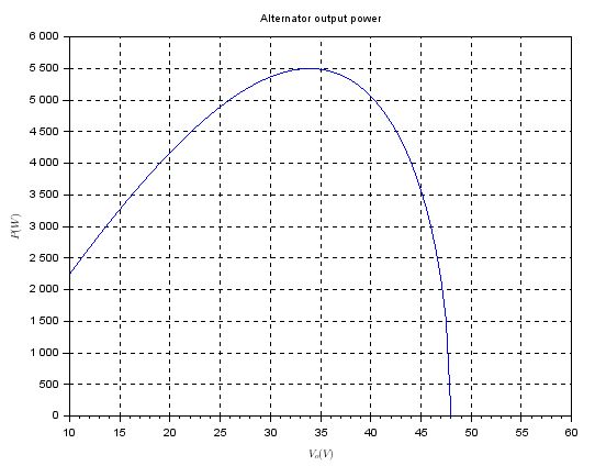
Graph from that question of Vout and Power out for a 12V Lundell alternator.

enter image description here

\$\endgroup\$

Your Answer

By clicking “Post Your Answer”, you agree to our terms of service and acknowledge you have read our privacy policy.

Not the answer you're looking for? Browse other questions tagged or ask your own question.