0
\$\begingroup\$

I have a source with variable power output during the time because it is shared with another devices and this source has not enough power to feed my load (a battery charger for a 1 cell 4.2V lipo) so when battery charger try to get a lot of current it downs de voltage of the source sometimes. To improve efficiency, I converted the source voltage with a buck dc-dc converter to a lower value, so current can be higher at the load, but this is not enough because load keeps asking for more current so source current increases also.

The ideal solution was a circuit so I can say "let pass all the current you can without dropping more than xx mV"(being this mV are setted by DAC).

¿what is the best way to solve this issue?


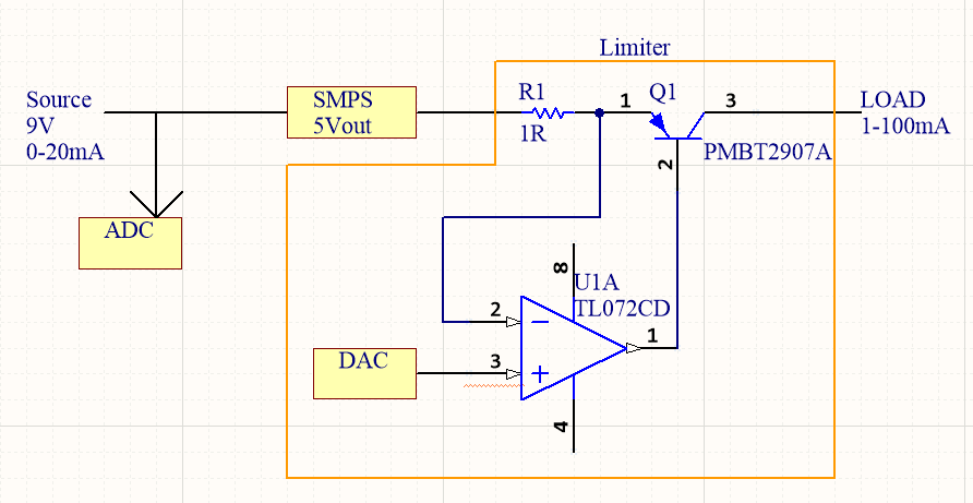
This is what I have now:

-SMPS buck power supply to convert 9 to 30Vin to 5Vout.

-PNP limiter programmed by non volatile DAC

limiter

Drawbacks of this:

-Non linear current selection. Only the first V select the gain of the circuit (amplification of the transistor). But even this first V doesn't have linear relationship with current.

-Digital feedback: Slow and not precise. I need to read the ADC at the input to know if voltage is dropping to extract a little bit less.

-Max current: with 1R at R1, the max current I can have is around 25mA. Can be enough for many of the situations, but it is reduced. I tried with different R1 values and circuit lost precision and I can't select only a few mA, wich is the main goal.


Edit:

This is how looks like after some improvements: limiter
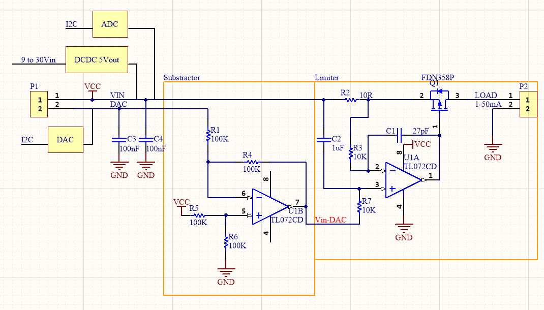

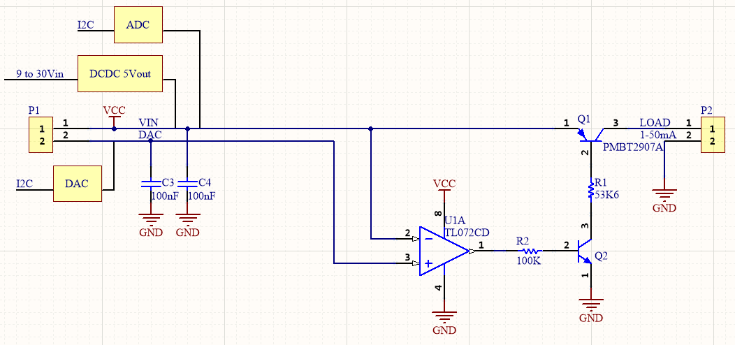
Edit 2: Go back to an easy solution. Need to fix the feedback loop of the operational amplifier. If at the input of R2 connects DAC directly works well, but it is needed to use digital loop (DAC/ADC) to maintain voltage at the input. limiter
\$\endgroup\$
10
  • 2
    \$\begingroup\$ Realize that almost all lab supplies don't have a "Limiter" to limit the current as it is not needed. They simply lower the output voltage such that a certain maximum current is maintained. To make a "current limiter" you'd need a regulator in series with the load. A voltage regulator has such a pass element already (usually a transistor). The "lower the output voltage" trick works just as well with switching supplies. \$\endgroup\$ Commented Jan 30, 2020 at 14:16
  • \$\begingroup\$ I've edited the schematic, and drawbacks are same as before, but the worst of this is the digital feedback. Ej: If after test source I setted current sink to 10mA and time after this source goes down I cannot recalibrate (to lower the current preset) until MCU reads ADC again. \$\endgroup\$ Commented Jan 31, 2020 at 12:26
  • \$\begingroup\$ Since this is just a battery charger, you may in future want higher currents, so choose a DC-DC converter than can be controlled and measure voltage & current. Then choose a suitable CC,CV cutoff with timer and power up test routine. This is the best way , ¿Isn't it? \$\endgroup\$
    – D.A.S.
    Commented Jan 31, 2020 at 20:05
  • \$\begingroup\$ I suggest that you study existing designs of voltage regulators with current limiting. Google for "lab supply schematic" and learn from that. Your new schematic raises so many questions (for example: What is C2 doing? There's no DC path form the left side of the sense resistor to the current regulator). I cannot see how this is going to work. Take this advise from an experienced circuit designer: if you want to design you need to study existing solutions and usually you just re-use those. Making your own circuits without that experience is bound to fail. \$\endgroup\$ Commented Jan 31, 2020 at 21:02
  • \$\begingroup\$ well, the limit can be as low as 2mA, up to maybe 100mA. And the DC-DC I know doesn't have too much precision. But anyway, the main problem here is the feedback loop to achieve this: "let pass all the current you can without dropping more than xx mV". Now this loop is digital but I don't think it is the best way to do this. \$\endgroup\$ Commented Jan 31, 2020 at 21:02

0

Your Answer

By clicking “Post Your Answer”, you agree to our terms of service and acknowledge you have read our privacy policy.