2
\$\begingroup\$

this is my first question on the site, so please let me know if there's something I can do to write it more helpfully.

The Problem: I'm building a small radio. At the output of my mixer, I need to build a narrowband filter at 455 kHz, and also convert the signal from double-ended to single-ended.

My Solution: Build a resonant LC filter that feeds a balun transformer. I first tried a shunt LC tank, which worked okay. But I realized that the filter was heavily dependent on exact L and C values, so I decided to try tuning it with a varactor (which would allow me to use L's and C's with looser tolerances). Unfortunately, varactors are very small, and the parallel inductance of my transformer placed a limit on how small I could make my capacitors.

So I decided to try out a series LC. Unfortunately, this put the mixer's \$R_{out}\$ in series with my inductor, which destroyed my Q. I was about to give up when I read this SE answer, which seemed to suggest that I could match a high impedance by adding a shunt capacitor.

On a whim, I threw in a 100nF cap... and it worked perfectly! My Q and insertion loss are both much better. But... why?

Here's my (simplified) circuit: enter image description here
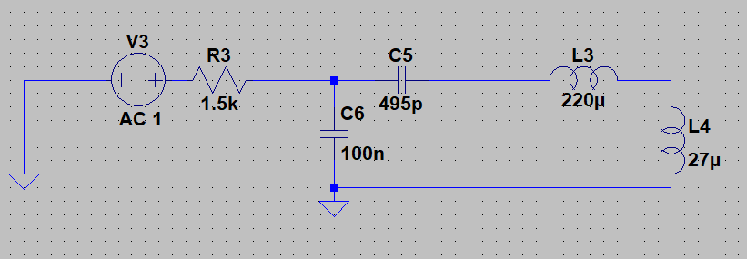
V3+R3 is my source, C5+L3 is my filter (L3 has \$R_{series}\$ = 250 mOhms), and L4 is my transformer ( \$R_{series}\$ = 75 mOhms).

Voltage across L4 without C6: enter image description here

And with C6: enter image description here

Learning is the goal of this project, so any advice / additional resources would be welcome. Thanks!

\$\endgroup\$
13
  • \$\begingroup\$ that looks like a slightly suboptimal pi network overall. also, radios using 455 kHz isn't an accident: radio designers "standardized" on that IF simply because it was easy to get accurate resonant components at exactly that frequency. \$\endgroup\$ Commented Mar 8, 2020 at 16:18
  • \$\begingroup\$ If you want to be fancy: excellent 455 kHz SAW filters exist. However, in modern times, it's much easier to get good filters for higher frequencies, so go through the SAW filters until you find a cheap one that matches your bandwidth/suppression/passband flatness needs and then put your IF where your filter is – IFs were always meant to be adapted to filters, not the other way around (which is why your varactor approach is kinda unusual). \$\endgroup\$ Commented Mar 8, 2020 at 16:27
  • \$\begingroup\$ C6 now shorts out R3 \$\endgroup\$
    – D.A.S.
    Commented Mar 8, 2020 at 16:32
  • \$\begingroup\$ if you want to stay linear: check out analog devices' excellent analog filter design wizard, which can plot filter impulse responses including "uncertainty ranges" with specifiable component tolerances. Cool tool. \$\endgroup\$ Commented Mar 8, 2020 at 16:32
  • \$\begingroup\$ This filter sim uses browser (save) and does any LC or active filter falstad.com/circuit/e-filt-hipass-af.html \$\endgroup\$
    – D.A.S.
    Commented Mar 8, 2020 at 16:34

2 Answers 2

1
\$\begingroup\$

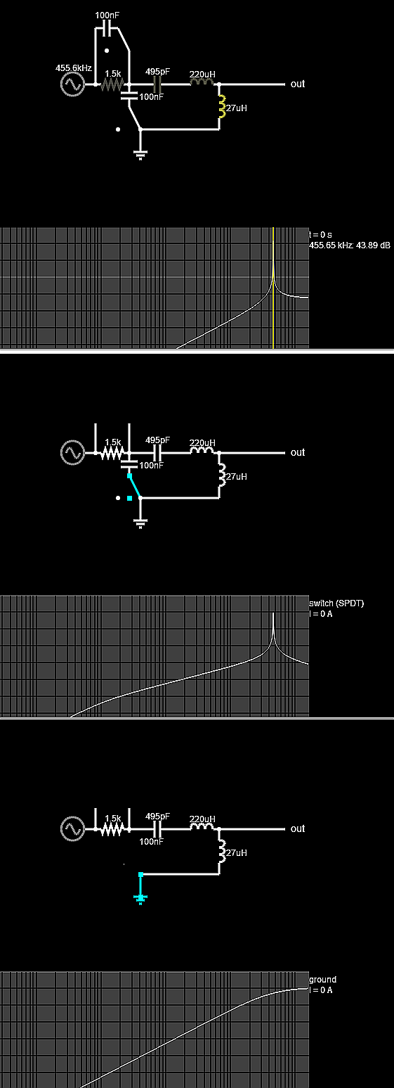
Your cap C6 closes the LC loop and becomes an impedance transformer with high Q LC filter with 44 dB gain or Q > 200 but then attenuated by 1k5 to -21dB loss.

I bypassed 1k5 to measure the Bode Plot.

If you followed my hint to use Falstad's filter analyzer, then you can make this with ideal switch and caps to compare with/without.

enter image description here

from +44 dB gain to -21dB loss.

\$\endgroup\$
4
  • \$\begingroup\$ Thanks for the detailed response! If I understand correctly, you're saying that without C6, the oscillating current must run through the loop (C5, L3, L4, V3, R3) which has low Q, but if we have C6 then the high-Q loop (C5, L3, L4, C6) oscillates instead? \$\endgroup\$
    – Adam Q
    Commented Mar 9, 2020 at 14:29
  • \$\begingroup\$ yes, limited only by ESR of each part \$\endgroup\$
    – D.A.S.
    Commented Mar 9, 2020 at 14:30
  • \$\begingroup\$ One thing I didn't get: What do you mean when you say "C6... becomes an impedance transformer"? I did the calculations by hand, and it looks like adding C6 doesn't change the input impedance of the filter very much. (8.06j ohms -> -6.18j ohms at 455kHz) \$\endgroup\$
    – Adam Q
    Commented Mar 9, 2020 at 14:32
  • \$\begingroup\$ That has to do with C ratios and L ratios \$\endgroup\$
    – D.A.S.
    Commented Mar 9, 2020 at 14:34
1
\$\begingroup\$

L/c resonators must have a complete circulating loop. That 0.1uf completes the loop, while placing the lossy resister across a fine parallel Z --- the cap you added.

\$\endgroup\$

Your Answer

By clicking “Post Your Answer”, you agree to our terms of service and acknowledge you have read our privacy policy.

Not the answer you're looking for? Browse other questions tagged or ask your own question.