0
\$\begingroup\$

I'm trying to design an unbalanced line input for an audio device using a single supply. I would like the input stage to provide variable gain between 0 and 2.

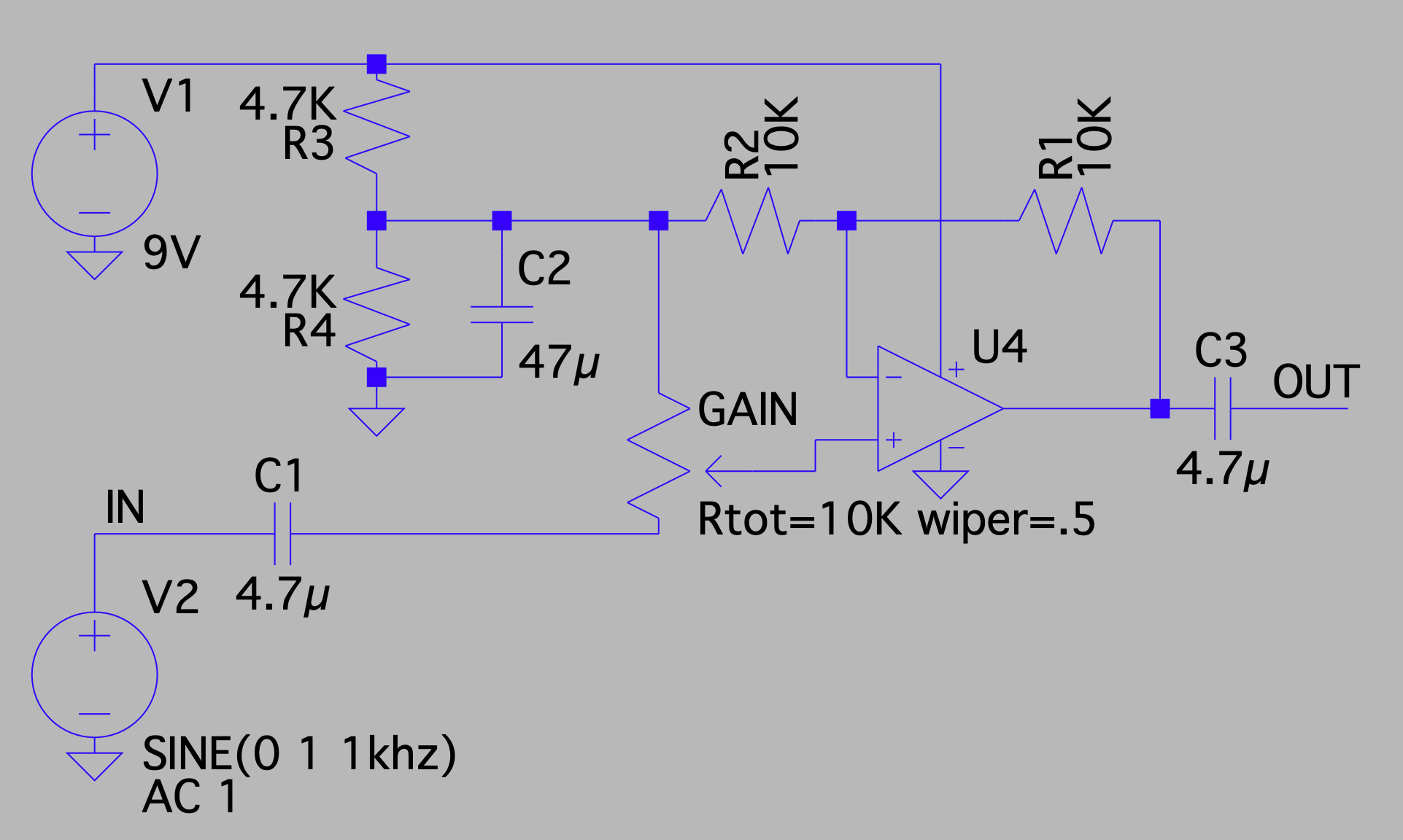
This is what I have come up with so far:

enter image description here

I have been running some basic simulations in LTspice that suggest the circuit is working as intended, so I hope I'm not too far off the mark.

However, I'm uncertain about a couple of things:

  1. Am I correct in assuming that the input impedance of the circuit equals GAIN + R4 (i.e 14.7K)?
  2. How do I calculate appropriate values for R1 and R2? 10K is just a guess...
\$\endgroup\$

1 Answer 1

1
\$\begingroup\$

Am I correct in assuming that the input impedance of the circuit equals GAIN + R4 (i.e 14.7K)?

For an AC input voltage, C2 can be assumed to dominate impedances and therefore your input impedance is purely the end-to-end value of your potentiometer (10 kohm).

How do I calculate appropriate values for R1 and R2? 10K is just a guess...
It’s a reasonable guess. You don’t want the values so low that your feedback network is taking several mA from the opamp output and, you don’t want them so high that parasitic capacitance ruins the top-end frequency response. 10 kohm is about right generally.

Use a simulation is my general advice for circuits like this.

\$\endgroup\$
4
  • \$\begingroup\$ Measuring the current across R1 in LTspice (using the expression "I(R1)") I get a value of -1.11 nA which seems very low? Could this be correct or am I doing something wrong? I'm using a model for the TL072 that I intend to use in the circuit... \$\endgroup\$
    – Rasmus B
    Commented Mar 15, 2020 at 14:56
  • \$\begingroup\$ That will be the DC current under static input conditions. You need to look at i(R1) when the input source is producing an AC waveform. \$\endgroup\$
    – Andy aka
    Commented Mar 15, 2020 at 17:25
  • \$\begingroup\$ Makes sense. I'm getting somewhat higher readings now but I stil have to reduce resistor values to 0.5K to get to 1 mA. I think I'll just breadboard it and measure the real thing. \$\endgroup\$
    – Rasmus B
    Commented Mar 15, 2020 at 18:34
  • \$\begingroup\$ Well, it all depends on the value of your input sinewave amplitude. More input means more current through the 10 kohm but, you can only go so far before the power supply voltage restricts the output waveform. \$\endgroup\$
    – Andy aka
    Commented Mar 15, 2020 at 19:15

Your Answer

By clicking “Post Your Answer”, you agree to our terms of service and acknowledge you have read our privacy policy.

Not the answer you're looking for? Browse other questions tagged or ask your own question.