0
\$\begingroup\$

I've an old device whose circuit is fried somewhere but since I want to modify this device, I don't want to find which component is fried, I simply want to plug it my own power supply instead. Luckily I have a second working device to test voltage and current wherever I want.

This device has a tiny coil activating a switch when current passes through it so I desoldered the wires on the working device to test this component. I tested both in DC and AC mode, here are the results:

  • Resistance: 64 Ohms
  • Voltage:

    • OL (DC)
    • 2.1 V (AC)
  • Current:

    • Entering the coil: 177 mA (DC) and 31 mA (AC)
    • Leaving the coil: 177 mA (DC) and 31 mA (AC) then slowly lowering to 30 mA (AC)

My question is: Can I deduce for sure this is an AC coil requiring an input of 2.1 V and 31 mA?

Also I know that assuming this is an AC coil I should in theory be able to input DC current as well. This way would be much more convenient since phone chargers or other kinds of everyday life transformers are often providing DC current.

So what would be the input power like if I choose to input DC instead of AC (assuming this coil is really an AC coil)? Is there an easy way to calcule the voltage and current I should apply?

EDIT: Additional information about the coil

Here is a photo of the coil. When a current passes through it, a magnetic field is created therefore attracting the metal plate. When this happens it activates a mechanical system which uses rotational energy from a 230V AC motor.

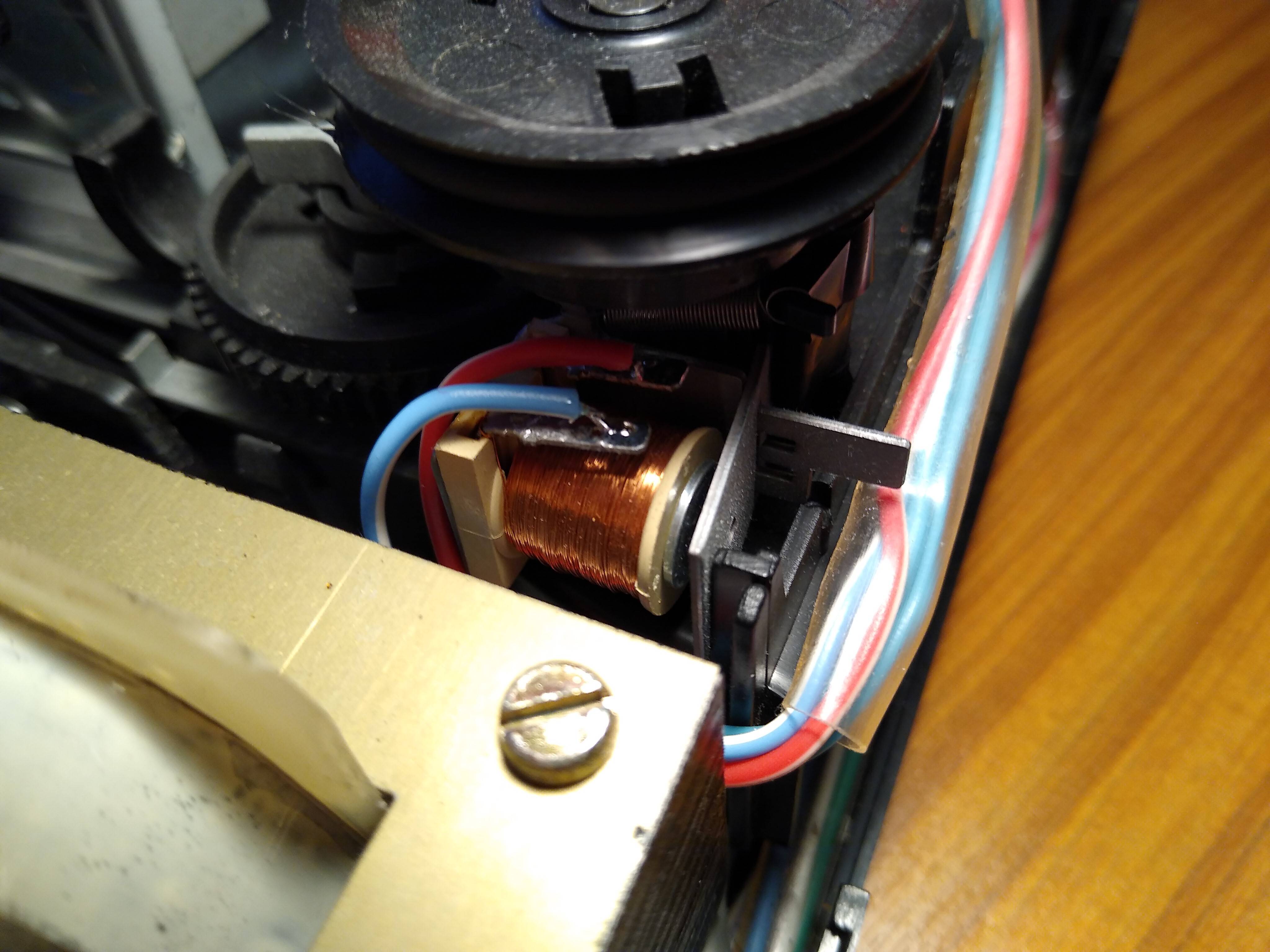
Photo of the coil

\$\endgroup\$
4
  • 1
    \$\begingroup\$ A "tiny coil activating a switch" sounds like a description of a relay. Can you share a photo of this device? \$\endgroup\$
    – The Photon
    Commented Mar 17, 2020 at 19:30
  • \$\begingroup\$ @ThePhoton I added a photo and additional explanation about this device. The coil is activating a mechanical system, it's not making electricity passing like a relay \$\endgroup\$ Commented Mar 17, 2020 at 20:15
  • \$\begingroup\$ That is a relay. I suspect it may be DC based on your measurments. Since your DC voltage read OL we know it is higher than your meter was set to read. The low voltage on AC and lower current in AC mode makes me suspect it is DC with lots of ripple (which looks like AC when you have your meter set that way). Set your meter so you can read the actual DC voltage on the working unit. \$\endgroup\$ Commented Mar 17, 2020 at 21:06
  • \$\begingroup\$ I did test again voltage in DC mode and the multimeter is showing OL all the time. I tried both in V and mV modes, I don't understand why. \$\endgroup\$ Commented Mar 18, 2020 at 9:52

1 Answer 1

1
\$\begingroup\$

My question is: Can I deduce for sure this is an AC coil requiring an input of 2.1 V and 31 mA?

No. Volts = Amps x Ohms. 0.177 A x 64 Ω = 11.38 V. The "OL" DC voltage reading means your meter was overloaded, perhaps because it was set to Ohms instead of Volts. The 2.1 V and 31 mA AC reading was probably ripple from the unregulated power supply.

My deduction is that the electromagnet is designed to operate from (approximately) 12 V DC.

\$\endgroup\$
7
  • \$\begingroup\$ I did test again voltage in DC mode and the multimeter is showing OL all the time. I tried both in V and mV modes, I don't understand why. I don't want to go for assumptions because that would be a disaster for me if I fry the coil. This is a project I started several months ago and it would be quite hard to find another of this exact old device. \$\endgroup\$ Commented Mar 18, 2020 at 9:51
  • \$\begingroup\$ Ok so I disassembled even more the device and found another relay which looks pretty much the same size. I followed the wires and one of them is linked to a 100μF 16V capacitor so probably this is the DC voltage I'm looking for. But now the big question is why is my multimeter showing OL when measuring voltage in DC mode? I'm 100% sure my probes don't touch each others \$\endgroup\$ Commented Mar 18, 2020 at 11:49
  • \$\begingroup\$ What brand/model is your multimeter? \$\endgroup\$ Commented Mar 18, 2020 at 20:10
  • \$\begingroup\$ Cheap one: Aneng an8008 \$\endgroup\$ Commented Mar 18, 2020 at 20:24
  • 1
    \$\begingroup\$ Most digital multimeters have a very slow response time, so a short voltage pulse may not give an accurate reading. The coil may produce a high voltage spike when switched off that is 'fooling' your meter. To see what is really happening you need an oscilloscope. \$\endgroup\$ Commented Mar 20, 2020 at 17:01

Your Answer

By clicking “Post Your Answer”, you agree to our terms of service and acknowledge you have read our privacy policy.

Not the answer you're looking for? Browse other questions tagged or ask your own question.