0
\$\begingroup\$

I have a offset printing machine and it's original electrical design uses a variac device to control it's speed (RPM) value of the main motor drive.

I don't have access to any electrical wiring diagram, so I need to find it's typical wiring diagram from variac device to motor.

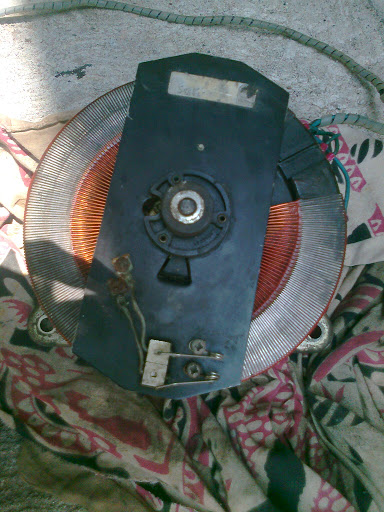
bellow picture is the front side of the variac. enter image description here

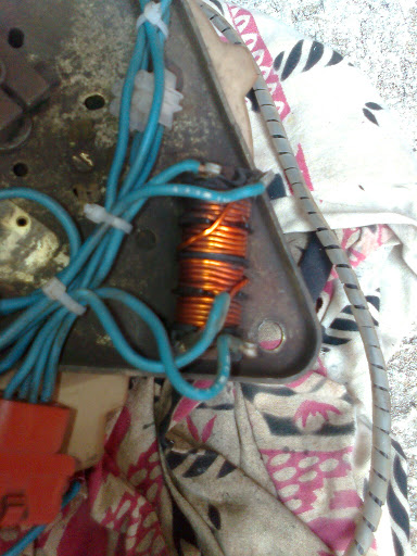
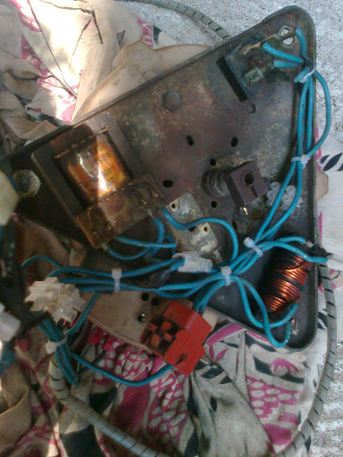
enter image description here I got four wires going into DC motor. And above is the backside of the variac device and it seems to me that, it goes through a inductor depicts as in bellow figure. What is the original purpose of that inductor? Is that a interpole motor which used to reduce the spaks on amateur brushes? Or is that for another purpose?

inductor coil

I need to know it's typical wiring diagram. How could I simply connect a DC motor to a variac?

--Thanks in advance--

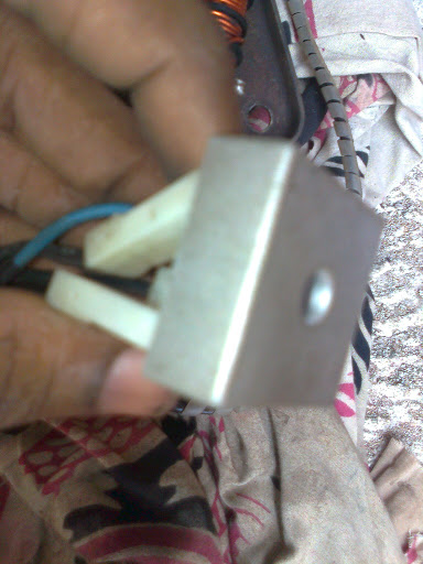
EDIT: I confirm that this is a DC motor, there are 2 rectifiers like these. enter image description here

\$\endgroup\$
6
  • \$\begingroup\$ What makes you think it's a DC motor? A variac is a transformer, and as such inherently deals with AC. 4 wires also makes it unlikely it is a DC motor, even if it wasn't known it is driven directly from a transformer. \$\endgroup\$ Commented Nov 17, 2012 at 13:52
  • \$\begingroup\$ sir there are a two rectifiers , variac output is rectified and then feeded through that coil and supply to that motor. \$\endgroup\$ Commented Nov 17, 2012 at 14:02
  • 1
    \$\begingroup\$ Once again you have focused on the background with thing you want to show in the foreground being blurry. You really need to learn how to use a camera before inflicting your pictures on others. \$\endgroup\$ Commented Nov 17, 2012 at 15:30
  • \$\begingroup\$ @Olin Lathrop , I could not understand what you telling. I'm not a camera expert. \$\endgroup\$ Commented Nov 17, 2012 at 15:33
  • 1
    \$\begingroup\$ You should be able to see for yourself that the item you are trying to show in the last picture is out of focus (blurry). It seems you focused on the stuff behind it (the background) since that is not blurry. \$\endgroup\$ Commented Nov 17, 2012 at 16:46

3 Answers 3

1
\$\begingroup\$

For safety, mechanically disconnect the motor from the printing press.
Some printing equipment can pretty much self destruct if run backwards.

AC/DC motors have brushes. Speed is controlled by voltage and physical load.
Generally two wiring schemes are used, parallel, and series.
Series wired, have good starting torque, and poor speed control,
so should not be started without a physical load.
Common series examples; car starters, vacuum cleaners, hand power tools.
Parallel wired, have better speed control, and lower starting torque.

Investigate the motor wiring. An ohm meter reading of each pair of wires will help.
Many AC/DC motors have access to the brushes on the outside of the motor.
If this is the case, carefully remove one of the brushes (paying attention to how it is installed).
Then re-test the wiring, to identify which pair power the armature through the brushes.

The press manufacture may be able to help, if they originally installed the motor.
If all else fails, plan on parallel wiring for the motor.
Many armatures have very low resistance, so would draw excessive power on starting.
The inductor may have been wired in series with the armature to reduce the starting surge.

Some printing equipment starts at a lower speed, then comes up to running speed.
The variac may have had an automatic power reduction mechanism when powered off,
so when started, it would start slower (lighter load), then come up to speed.
If this is a small press, the operator may just set the speed and have a start/run switch.

The motor wiring also determines motor turning direction.
Verify motor direction, before mechanically reconnecting.
Once connected, turnover the press by hand first, to see nothing is binding before power is applied.
\$\endgroup\$
2
\$\begingroup\$

You can't directly. A variac is a transformer, usually a autotransformer, but in either case puts out AC.

You could rectify the AC to make DC by using a full wave bridge if you truly have a DC motor.

More likely, what you have is not a DC motor. This machine looks old, and considering it was intended to have variable speed, it could be a brushed motor that is commutated so as to work directly with AC. Such motors do work with DC too, but always spin in one direction regardless of the polarity of the applied voltage.

This is just a guess, but the extra stuff on the bottom of the variac could be for automatically moving the wiper as part of a control system.

\$\endgroup\$
1
\$\begingroup\$

If it is a DC motor then 4 wires DOES make sense. 2 wires are for the field winding (the magnet made with DC) and the others are for the Armature (the ones that make power). The Field winding will be hooked up to its own bridge, runnig full voltage all the time to maintain the magnetic field inside the motor. The Armature winding will be hooked up to a (ususally) bigger rectifier and the variac and this is the driving voltage that you will use vary the speed of the motor.

It looks like a tiny one... I use up to 5hP. Be careful with these if you run 240V because 240VDC is like 600VAC as far as arcing potential and should be treated with respect!

\$\endgroup\$
1
  • \$\begingroup\$ +1 For correct understanding. More often these days an SCR phase control is used to control the armature with a bridge for the (low current) field windings. See, for example, KBC's wiring diagrams. Variacs are pretty much indestructible if you properly fuse them but SCR controls are cheaper and can provide better speed regulation via IR compensation. \$\endgroup\$ Commented Sep 26, 2014 at 15:26

Your Answer

By clicking “Post Your Answer”, you agree to our terms of service and acknowledge you have read our privacy policy.

Not the answer you're looking for? Browse other questions tagged or ask your own question.