3
\$\begingroup\$

I'm pretty new to avr programming. I'm facing a strange problem that I can't solve so far.

I've wrote a simple code:

#include <avr/io.h>
#include <util/delay.h>

int main(void) {

    DDRA = 0XFF;

    for (;;){
        PORTA = 0xFF;
        _delay_ms(1000);
        PORTA = 0x00;
        _delay_ms(1000);
    }

    return 0x00;
}

I'm setting the F_CPU (the value used by _delay_ms() ) trough the Makefile I'm using to compile and upload the code:

DEVICE     = attiny84
CLOCK      = 20000000
PROGRAMMER = -c usbasp -P /dev/tty.usb* -b 19200 
OBJECTS    = main.o dallas_one_wire.o
FUSES      = -U lfuse:w:0x62:m -U hfuse:w:0xdf:m -U efuse:w:0xff:m


######################################################################
######################################################################

# Tune the lines below only if you know what you are doing:

AVRDUDE = avrdude $(PROGRAMMER) -p $(DEVICE)
COMPILE = avr-g++ -Wall -Os -DF_CPU=$(CLOCK) -mmcu=$(DEVICE)

# symbolic targets:
all:    main.hex

.c.o:
    $(COMPILE) -c $< -o $@

.S.o:
    $(COMPILE) -x assembler-with-cpp -c $< -o $@
# "-x assembler-with-cpp" should not be necessary since this is the default
# file type for the .S (with capital S) extension. However, upper case
# characters are not always preserved on Windows. To ensure WinAVR
# compatibility define the file type manually.

.c.s:
    $(COMPILE) -S $< -o $@

flash:  all
    $(AVRDUDE) -U flash:w:main.hex:i

fuse:
    $(AVRDUDE) $(FUSES)

install: flash fuse

# if you use a bootloader, change the command below appropriately:
load: all
    bootloadHID main.hex

clean:
    rm -f main.hex main.elf $(OBJECTS)

# file targets:
main.elf: $(OBJECTS)
    $(COMPILE) -o main.elf $(OBJECTS)

main.hex: main.elf
    rm -f main.hex
    avr-objcopy -j .text -j .data -O ihex main.elf main.hex
# If you have an EEPROM section, you must also create a hex file for the
# EEPROM and add it to the "flash" target.

# Targets for code debugging and analysis:
disasm: main.elf
    avr-objdump -d main.elf

cpp:
    $(COMPILE) -E main.c

Regarding the attiny84's data sheet, it should run at 20Mhz under 5 volts.

Unfortunately the led isn't blinking at a rate of 1 every second but somewhat really longer around a 10 secs rate.

By tuning the F_CPU value, I've reached the 1 second blinking rate by using F_CPU = 1000000 (1Mhz)

Does that means that the attiny84 is running a 1Mhz or am I wrong somewhere else ?

\$\endgroup\$
1
  • 1
    \$\begingroup\$ By default the attiny is running off it's internal oscillator that is 8Mhz and also by default there is a clock divide by 8 fuse set. So as you figured out the hard way, it is running at 1Mhz. You can disable the divide by 8 fuse to get 8Mhz, but anything higher you will need to add an external crystal. Also FYI the internal oscillators are not very accurate, it doesn't matter in this case but it's good to know. \$\endgroup\$ Commented Nov 27, 2012 at 22:59

2 Answers 2

5
\$\begingroup\$

Assumption: You are driving the ATTiny84 with its internal RC clock.

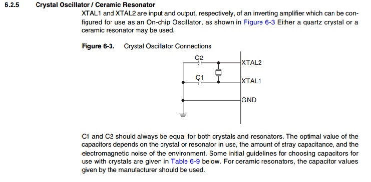
In order to have the ATTiny84 running at 20 MHz, the microcontroller will need to be provided an external 20 MHz clock, typically achieved by a 20.0 MHz crystal or resonator and two load capacitors. From the datasheet:

Crystal Oscillator

Also, you will have to set the fuses appropriately for the microcontroller to use an external oscillator instead of the internal one.

You can calculate the fuse setting bits you need for external crystal, by selecting the specific AVR here. Additional useful information in this answer to a related question on this site.

\$\endgroup\$
2
\$\begingroup\$

The ATtiny is indeed running at (approximately) 1MHz.

From the datasheet:

6.2.6 Default Clock Source

The device is shipped with CKSEL = “0010”, SUT = “10”, and CKDIV8 programmed. The default clock source setting is therefore the Internal Oscillator running at 8.0 MHz with longest start-up time and an initial system clock prescaling of 8, resulting in 1.0 MHz system clock. This default setting ensures that all users can make their desired clock source setting using an in-system or high-voltage programmer.

Chapter 6.2 explains how clock selection for this ATtiny works, but be careful, selecting too slow clock frequency (eg. 128kHz) can prevent you from reprogramming the device unless you use a "high voltage" programmer. The fuses use negative logic, read the chapter carefully before programming them.

Table 19-5 explains the 'Fuse Low Byte' has a default 0x62 value, where bit7 is 0 but indicates that the 8MHz clock is divided by 8. (hence negative logic).

Many applications run perfectly well at the lower clock, which has the advantage of lower power use. It totally depends on your application whether you really need a higher clock or not. Just set F_CPU to the applicable value. F_CPU informs the compiler about how fast the controller clock is, it does not set the controller's clock.

\$\endgroup\$
1
  • \$\begingroup\$ Thanks your explenation is really worth and goes beyond my question! Appreciated \$\endgroup\$
    – Kami
    Commented Nov 28, 2012 at 1:30

Your Answer

By clicking “Post Your Answer”, you agree to our terms of service and acknowledge you have read our privacy policy.

Not the answer you're looking for? Browse other questions tagged or ask your own question.