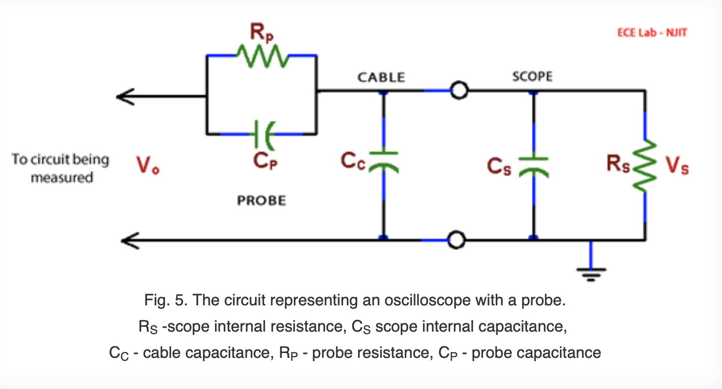
I'm trying to understanding input impedance and its circuitry of a simple, passive oscilloscope 10x probe. From reading Input Impedance of an Oscilloscope and the video EEVblog #453 - Mysteries of x1 Oscilloscope Probes Revealed, I don't understanding why we add these capacitors in the probe circuitry and make things more complicated. The point is to add enough impedance to a passive probe to minimize loading effect of the circuit being measured. A big enough resistor will do and the with just resistors, voltage divider works the same for both AD and DC source regardless of frequencies. If there are intrinsic reactances in the wiring, then can't we just add a big enough resistor in series with those to make any reactance negligible?
-
\$\begingroup\$ "Can't we just add a big enough resistor in series with those to make any reactance negligible" At the expense of sensitivity? and noise? And bandwidth? Remember, RC time constants are a thing. \$\endgroup\$– DKNguyenCommented May 23, 2020 at 18:20
3 Answers
I don't understanding why we add these capacitors in the probe circuitry and make things more complicated.
They make things far less complicated. The low-pass filter that would otherwise occur is eliminated.
The point is to add enough impedance to a passive probe to minimize loading effect of the circuit being measured. A big enough resistor will do and the with just resistors, ...
No. Increasing the probe resistance decreases the high-pass cut-off as it will be proportional to \$ \frac 1 {RC} \$.
... voltage divider works the same for both AD and DC source regardless of frequencies.
No. You have omitted the effect of the scope's input capacitance.
If there are intrinsic reactances in the wiring, then can't we just add a big enough resistor in series with those to make any reactance negligible?
Increasing the resistance decreases the signal available to the 'scope to the point that you won't be able to get high enough resolution and ADC noise will become a problem.
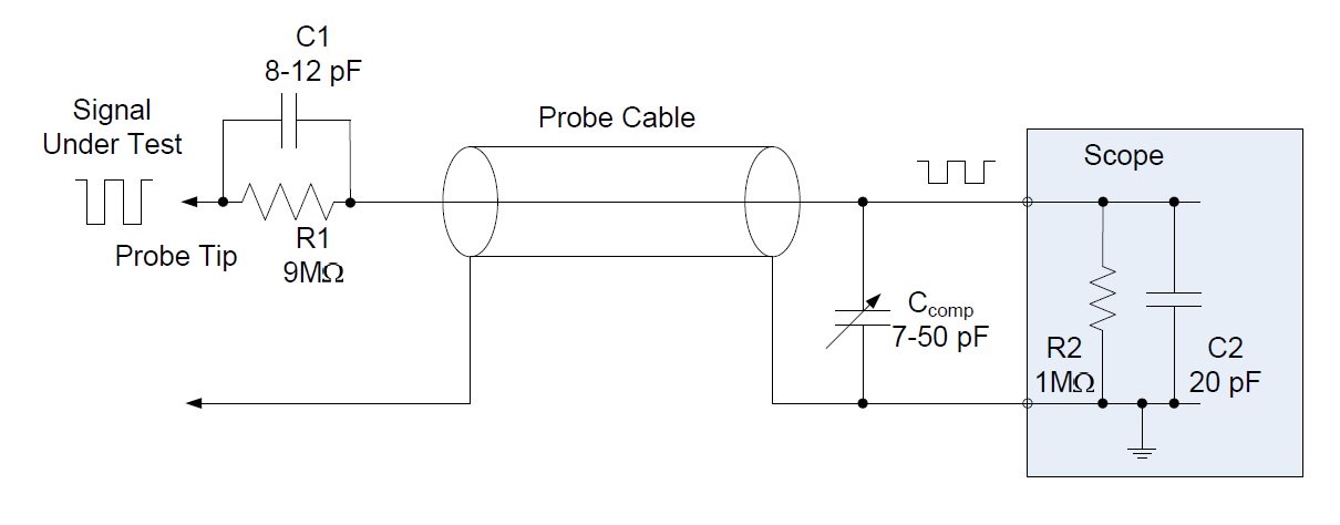
Figure 1. From Introduction to oscilloscope probes.
The trick is to use two potential dividers; one resistive and one capacitive. Since we've got a ratio of 9:1 with the resistive divider we need to do the same with the capacitive divider. Remember that the capacitors impedance is given by \$ Z_C = \frac 1 {2\pi fC} \$ so $$ \frac {R_1}{R_2} = \frac 9 1 = \frac {Z_{C1}}{Z_{C2}} = \frac {\frac 1 {2\pi fC_1}} {\frac 1 {2\pi fC_2}} = \frac {C_2}{C_1}$$
From this we get \$ C_2 = 9C_1 \$. With the values shown in Figure 1 we can just about achieve this if C1 is 8 pF and CCOMP is wound up to the max to give us 72 pF total (although this model omits the cable capacitance so we have room to spare).
-
\$\begingroup\$ from the circuit diagram I can't see if the probe is grounding total capacitance or total resistance. Does it form a high pass (grounding resistor) or low pass filter (grounding capacitor) at the tip? \$\endgroup\$– KMCCommented May 24, 2020 at 9:25
-
\$\begingroup\$ Everything outside the blue box is in the scope probe and lead. The probe tip doesn't ground anything. It's the combination of the probe and the oscilloscope that provides the load between the tip and ground. \$\endgroup\$ Commented May 24, 2020 at 11:12
-
\$\begingroup\$ A low pass filter takes in signal through a resistor with a parallel capacitor to ground, and vice versa for high pass filter. In the schematic, both R2 and C2 goes to ground in parallel, while both C1 and R1 takes in signal in parallel. Neither of them forms a low pass or high pass filter. \$\endgroup\$– KMCCommented May 25, 2020 at 6:58
-
\$\begingroup\$ Have you tried simulating the various configurations? \$\endgroup\$ Commented May 25, 2020 at 7:10
-
\$\begingroup\$ assume we achieve a \$C_{2} = 9C_{1}\$ ratio with 8pF and 72pF and having their reactances, say on a 50Mhz signal, are \$398\Omega\$ and \$44\Omega\$. The input impedance for high frequency signals is only \$442\Omega\$, so much more lower than that given by the resistor pair in lower frequency range or DC (\$10M\Omega\$). Does that mean if the input signal frequency goes high enough where capacitors reactance dominates, the input impedance of the scope significantly decreases resulting in a higher loading effect? \$\endgroup\$– KMCCommented Sep 2, 2020 at 7:13
The cable has capacitance, and the scope input has also capacitance. If you add resistance, it would just reduce the bandwidth.
That's why you add capacitance to the probe, to nullify the other capacitances.
Basically it's the same thing with the resistances and the capacitances. If you want a 10x probe, and scopes have 1M resistance, you add 9M so that it divides DC voltages by 10. If you want also the AC waveforms to attenuate by 10x, and you already have some capacitances in the system, you select a correct capacitance to get 10x attenuation.
-
\$\begingroup\$ I was going to post a picture showing how RC can perform perfect signal reconstruction. If you want to, feel free to add it. Maybe a picture will say a thousand words? \$\endgroup\$ Commented May 23, 2020 at 18:31
-
\$\begingroup\$ Is that the scope capacitance form a low pass filter and adding capacitor to the probe tip to form a high pass filter? \$\endgroup\$– KMCCommented May 24, 2020 at 9:29
You cannot take off Cs nor Cc. Together with Rp they would make a RC lowpass filter. Elementary impedance calculations reveal that the low-pass filtering effect can be compensated by adding Cp. You can consider it a high frequency boost. The total loading of the circuit under measurements is still lighter than without the probe.
General rule for flattest frequency response: RpCp=Rs(Cc+Cs) That's useful as long as the cable is short enough. As the frequency grows the user must finally take into the account that the cable is actually a transmission line which is badly matched at both ends. The compensation becomes gradually worse as the frequency grows. There's no strict limit when this happens.
-
\$\begingroup\$ I'm confused. So is the compensation Cp for maintaining 10:1 impedance ratio at high frequencies? Or is the compensation to equate the time constance between tip's RC and scope+cable's RC? Or Cp is added as a high pass filter on top of the scope's RC low pass filter? \$\endgroup\$– KMCCommented May 24, 2020 at 9:38
-
\$\begingroup\$ It does these all at the same time. The impedance ratio must be calculated by taking into the account Cs and Cc, too. The total impedance decreases as the frequency increases, but it's 10x the impedance made by Cs, Cc and Rs. If you cannot do elementary circuit math you can try to see the effect with simulation. \$\endgroup\$– user136077Commented May 24, 2020 at 9:43


