0
\$\begingroup\$

I'm learning about op amps and I have the following problem. I need to make a circuit using one op amp that give me the following output (Vi input, Vo output)

enter image description here enter image description here

I know that the output will be like $$ v_o = 4\,v_i+6 $$ So I assume that I can make this work with an additive non-inverter amplifier, where one of the inputs will be the 6 V offset. I think that a configuration like this is what I need

enter image description here

I found that the equation for the output in this case will be this $$ v_o=\left(\frac{R_f}{R_s}+1\right)\left(\frac{1}{R_1}+\frac{1}{R_2}\right)\left(\frac{v_i}{R_1}+\frac{V_2}{R_2} \right) $$ And then I played around with the resistors but I didn't reach anywhere. I dont know what I am missing

\$\endgroup\$
10
  • \$\begingroup\$ Can you explain more about what you mean by "didn't reach anywhere"? Are you talking about the fact that you couldn't find resistor values that worked for you? Or that you actually tried to make this circuit and it didnt work? \$\endgroup\$
    – BeB00
    Commented May 25, 2020 at 3:00
  • \$\begingroup\$ masteringelectronicsdesign.com/… \$\endgroup\$
    – BeB00
    Commented May 25, 2020 at 3:08
  • \$\begingroup\$ Do you know how to make any balanced differential amplifier with a gain of x4 without offset? \$\endgroup\$
    – D.A.S.
    Commented May 25, 2020 at 3:08
  • \$\begingroup\$ I'm not sure if I need to set Rs and Rf first and work from there or from where I need to start. I'll check your link @BeB00 \$\endgroup\$
    – Emiliano
    Commented May 25, 2020 at 3:28
  • \$\begingroup\$ I can make the circuit for a 4x gain. But I'm not sure how to add the offset @TonyStewartSunnyskyguyEE75 \$\endgroup\$
    – Emiliano
    Commented May 25, 2020 at 3:31

4 Answers 4

2
\$\begingroup\$

Opamps amplify AC signals and DC signals alike. In this case, you know you want a gain of 4, so look up an op amp summation circuit: one input will be your AC signal centered around 0V and the other input will be a DC offset BEFORE the amplification gain. So in your case, I'd use a voltage divider to get a 1.5 V input level and sum that with your AC signal. Once it's amplified you'll have your 4 Vp2p + 6 VDC.

Edit: Also regarding the voltage divider, make sure that the resistor values you're using to generate your 1.5 V DC offset are an order of magnitude lower than your addition stage resistors, you don't want your 1.5 VDC offset to be too high of an impedance that it gets dragged around by what I assume is a low impedance 1 Vp2p input sine wave source. In other words, if your voltage divider resistors form a 1 kOhm impedance voltage source, I would suggest that your summing resistors on the opamp input should be at least 10 kOhm.

\$\endgroup\$
3
  • \$\begingroup\$ That's what I'd hoped someone would answer towards, though I think you could expand your answer a bit more than this. In my book it doesn't quite rate a +1, though still quite correct. \$\endgroup\$
    – jonk
    Commented May 25, 2020 at 3:53
  • \$\begingroup\$ Thank you, that was really helpful \$\endgroup\$
    – Emiliano
    Commented May 25, 2020 at 4:09
  • \$\begingroup\$ Okay. That's good enough!! +1. And thanks! \$\endgroup\$
    – jonk
    Commented May 25, 2020 at 4:42
1
\$\begingroup\$

Ideally you’d like the input impedance to be high. There are at least two good reasons to violate that principle- if the input exceeds the supply (more specifically the amplifier input common-mode range) or if the gain is less than 1 for a non-inverting configuration. Neither is true here. So let’s try to add the offset to a non-inverting gain-of-4, with standard 1%- tolerance resistors we can use 10K and 30K to get a nominal gain of 1+30K/10K = 4.

If we return the 10K to a voltage other than ground we can add an offset. The gain looking into the 10K resistor is -3 so a voltage of -2V will yield an output offset of +6V. If you have a reference voltage of more negative than -2V (for example, a -2.5V shunt reference) you can create a Thevenin equivalent using 2 resistors with -2V open-circuit voltage and 10K source resistance. In that example the required resistors would be 12.5K and 50K.

schematic

simulate this circuit – Schematic created using CircuitLab

enter image description here

\$\endgroup\$
1
  • \$\begingroup\$ That's really cool, I hadn't thought of it that way. I just started learning about this, so your answer took me a little bit of time to understand. Thank you \$\endgroup\$
    – Emiliano
    Commented May 25, 2020 at 4:57
0
\$\begingroup\$

After some self-confidence of doing it the proper way with KVL to get the transfer function \$v_o/v_i\$ to apply gain and offset you learn how to do it from memory.

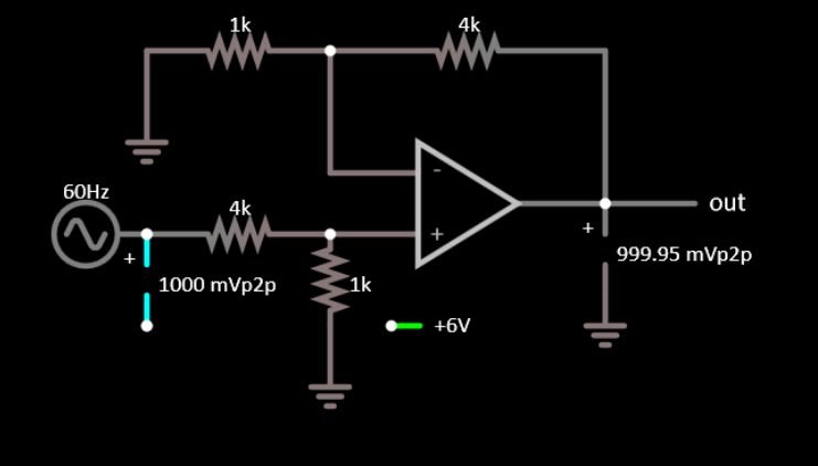
Gain 4x, no offset enter image description here

Gain 1x , no offset enter image description here No I ask you what is the correct configuration for gain=4x and offset =+6?

\$\endgroup\$
2
  • \$\begingroup\$ Well the first one have the gain that I need, but none of them adds the offset \$\endgroup\$
    – Emiliano
    Commented May 25, 2020 at 3:34
  • \$\begingroup\$ think harder... how do you get unity gain on 6Vdc offset? and 4x gain on \$v_i\$ \$\endgroup\$
    – D.A.S.
    Commented May 25, 2020 at 4:04
0
\$\begingroup\$

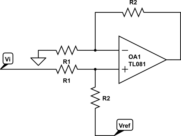
schematic

simulate this circuit – Schematic created using CircuitLab

The final formula boils down to: \$ V_{o} = \frac{R_2}{R_1}\;V_{i} + V_{ref}\$

With \$ \frac{R_2}{R_1} = 4 \$ and \$ V_{ref} = 6 \$, you get what you want.

\$\endgroup\$

Your Answer

By clicking “Post Your Answer”, you agree to our terms of service and acknowledge you have read our privacy policy.

Not the answer you're looking for? Browse other questions tagged or ask your own question.