I have designed a 4-20 mA PID controller using an ATmega328P, an MCP4922 (DAC), and an XTR115UA (4-20 mA current loop transmitter).
I used the circuits proposed in the datasheets and the PCB and schematic files are linked.
Please have a look and give feedback on the layout or schematics; will this work or fail?
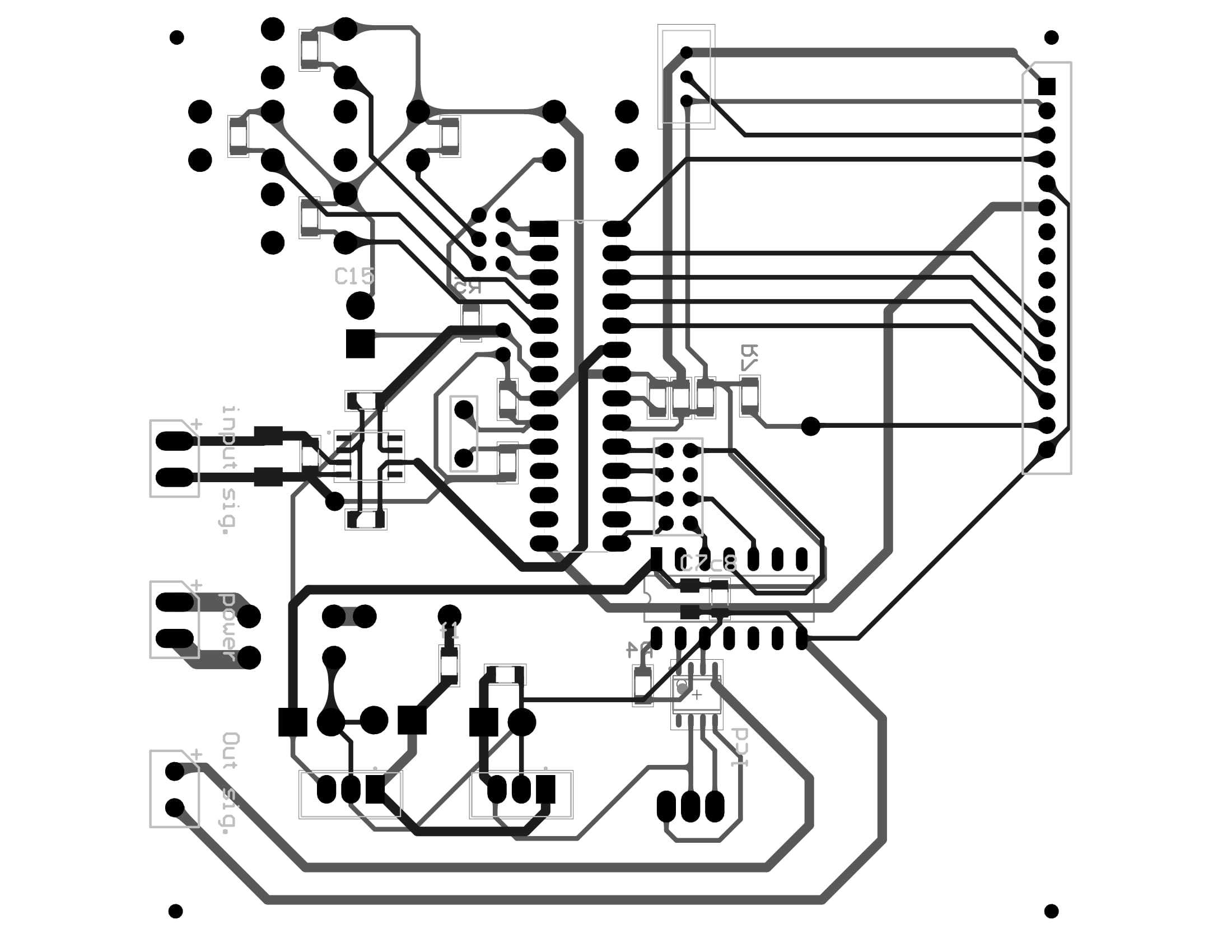
Is it helpful to use a polygon pour on both the top and bottom layers and connect one layer to Vcc and another to GND?
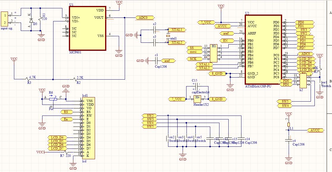
Here are the schematics and PCB.
This is where the 4-20 mA input signal comes in and is converted to a 0-5 V voltage with an MCP601 op-amp. The result goes to the uC:
5 V supply:
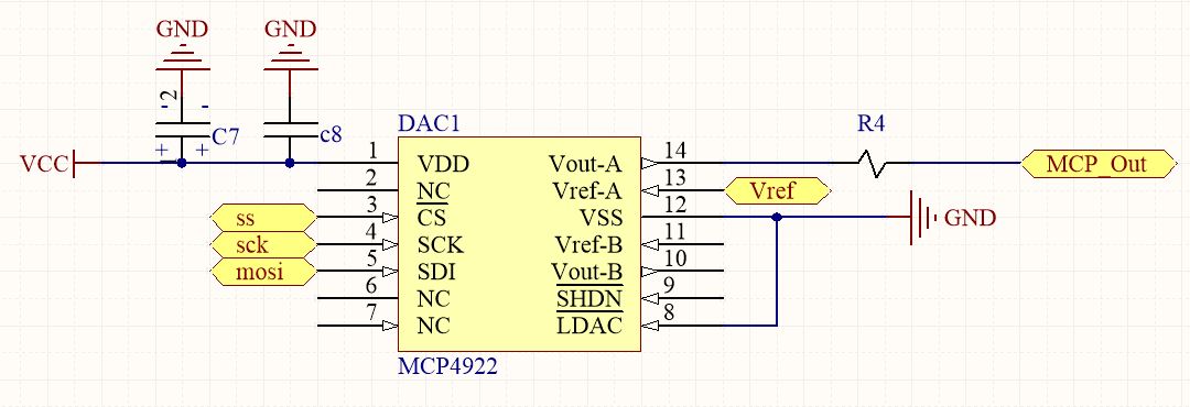
The uC output is sent to the DAC:
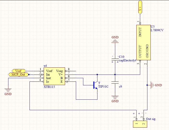
The DAC drives the XTR115 current loop transmitter:
The 7809 produces Vloop and the 4-20 mA output signal goes to an 180 Ω coil.
This is the layout:


