0
\$\begingroup\$

i have a rf-system that is working in frequency range of 100 MHz and try to match the impedance of the load to the source system (50 Ohm).

So, in general, i know that a network (P- or T-Network) has to be placed between the source and the load to maximize the power transmission between both. This should look like this one:
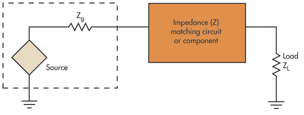
enter image description here

There also certain calculation rules to calculate the values of the matching circuit to fit between the source and the constnt load at the given frequency.

But know, i dont have a fixed impedance but an impedance curve over a frequency range in which i want to have the best coupling between the systems. The impedance load looks like this one here:
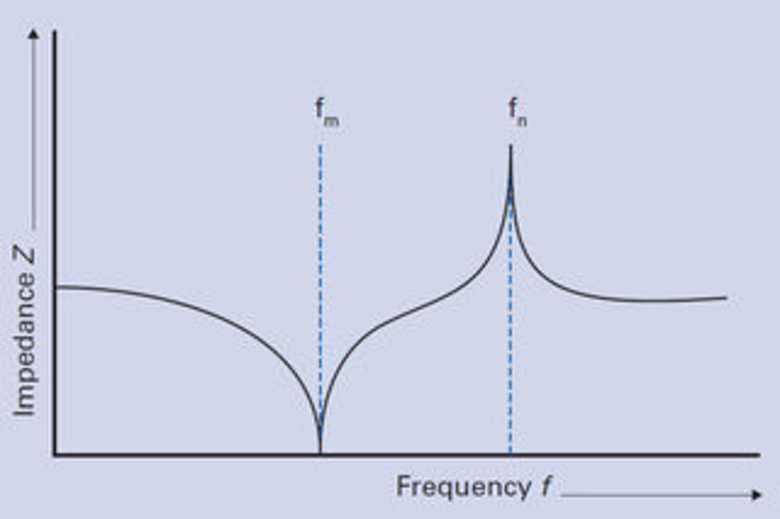
enter image description here


Do you know a good way to make the impedance matching circuit operating in a given frequency range for a given impedance curve. What is a good method to use for this kind of problem.

Thank you in advance!

\$\endgroup\$

1 Answer 1

0
\$\begingroup\$

In general, a method to match such a network can be started by looking at the cause of the impedance shift. In your example, it would apear you have a resonant short at \$f_m\$ and resonant shunt at \$f_n\$. If you model those with poles and zeros you can tune them out in a more complex matching network.

More advanced would be using a method where you do some kind of polynomal fitting of your load. You can then use that in your matching network equations to generate the neede impedances versus frequency to match this, and then see if you can find a easy way to implement them with L/C/resonators/transmissionlines and so on.

\$\endgroup\$

Your Answer

By clicking “Post Your Answer”, you agree to our terms of service and acknowledge you have read our privacy policy.

Not the answer you're looking for? Browse other questions tagged or ask your own question.