Which is used to convert analog input signal to PWM output. How can I vary the output with the input? How I can vary duty cycle?
\$\begingroup\$
\$\endgroup\$
3
-
\$\begingroup\$ Welcome to the site. Please note that it's not a free design house. People will help you take the next step if your question shows you've done as much as you possibly could on your own - which yours doesn't, I'm afraid. Please edit your question and greatly improve it. Show your own work and own findings so far in considerable detail with a schematic. The schematic tool here is easy to use. The better the quality of question, the better the quality of the answers you will attract. Again, a very warm welcome. \$\endgroup\$– TonyMCommented Jun 17, 2020 at 11:15
-
\$\begingroup\$ Does this answer your question? Is building a DC-DC PSU PWM controller from discrete components a terrible idea? - see my answer. \$\endgroup\$– Andy akaCommented Jun 17, 2020 at 11:32
-
\$\begingroup\$ You cannot begin without specs. % min, max etc \$\endgroup\$– D.A.S.Commented Jun 17, 2020 at 13:36
Add a comment
|
1 Answer
\$\begingroup\$
\$\endgroup\$
3
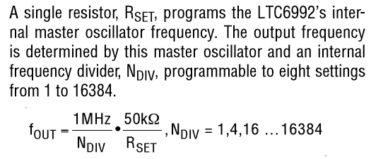
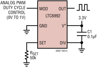
Look at the LTC6992, it converts voltage to PWM.

Source: https://www.analog.com/en/products/ltc6992-1.html#product-evaluationkit
-
\$\begingroup\$ The capacitor and the resistor(Rset) is inbuilt in IC or have to provide externally \$\endgroup\$– TEC HUBCommented Jun 18, 2020 at 1:34
-
\$\begingroup\$ Rset is the one shown above in the diagram, that is all you need to set the frequency \$\endgroup\$– Voltage Spike ♦Commented Jun 18, 2020 at 3:50
-
\$\begingroup\$ Man, the price! I am amazed \$\endgroup\$ Commented Sep 8, 2021 at 11:22

