0
\$\begingroup\$

I'm designing the front-end circuitry for an ADC. The ADC is to be used to read from sensors under two use conditions:

  1. An externally referenced sensor, whose signal line will either be 0-5V or bipolar (e.g. ±10V). Note that the ADC supports bipolar inputs. No additional circuitry is required to support this scenario.
  2. An unreferenced two-wire sensor, whose signal line will need to be pulled up to a 5V reference via a 1kOhm resistor within my front-end circuitry before interfacing with the ADC. A basic representation of this scenario is shown as follows:
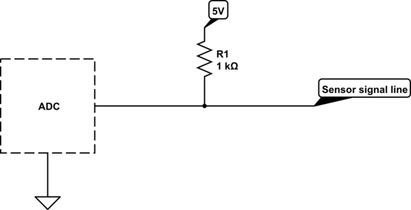
schematic

simulate this circuit – Schematic created using CircuitLab

The user can install sensors of either scenario, so my front-end circuitry needs to be able to support both operating modes. My initial design was to use an MCP23017 (or another similar I/O expander) which could provide the 5V reference to the sensor signal line by setting that particular MCP23017 pin as a logic high output. Similarly, it could be set as a high impedance input to support scenario 1 (i.e. no affect on the sensor signal line). However, as the sensor signal line can be both negative and much higher voltage than the MCP23017 VDD, I don't think this method is suitable. Even if the MCP23017 pin could be set to a high impedance input, there's always the risk that the user accidentally enables the pullup reference on a particular input, damaging the MCP23017.

Could I use a similar approach, but instead use the MCP23017 pin (as an output) to turn on/off a transistor? If so, would an n-type MOSFET be the best option? What considerations need to be made to ensure the circuit is open (so far as reasonably practicable) for scenario 1 operation (i.e. no affect on externally referenced sensor signal line) and closed for scenario 2 operation (i.e. as close as possible to exactly 1kOhm series resistance to 5V reference)? Similarly, are there any other considerations from a protection perspective, allowing for bipolar inputs which are greater than 5V? I.e. the circuit should not be at risk if a -~20V signal is connected with the transistor in either the on or off state.

\$\endgroup\$

1 Answer 1

1
\$\begingroup\$

Consider this maybe: -

MCP23017 absolute maximum ratings say: -

Maximum output current sourced by any output pin.......................25 mA

If the output pin is set at 5 volts and the input is down at -10 volts then, the maximum current taken is: -

$$\dfrac{\text{15 volts}}{\text{1000 ohms}}$$

This is 15 mA.

MCP23017 absolute maximum ratings also say: -

Maximum current into VDD pin .......................................125 mA

So the chip can support 125/15 ADC inputs in this state = 8 ADC lines

If the pull up resistor can be larger in value you'll get more pins available.


Could I use a similar approach, but instead use the MCP23017 pin (as an output) to turn on/off a transistor? If so, would an n-type MOSFET be the best option?

Yes you could and a P-channel MOSFET would be your best option because it will pull-up the resistor to the positive rail more effectively and simply than an N-channel device.

What considerations need to be made to ensure the circuit is open (so far as reasonably practicable) for scenario 1 operation?

Well, you might get circa 1 μA leakage through the MOSFET when it is disabled and this might be a problem.


Are there any other considerations from a protection perspective, allowing for bipolar inputs which are greater than 5V? I.e. the circuit should not be at risk if a -~20V signal is connected with the transistor in either the on or off state.

Here's where you are going hit problems with either a MOSFET or the MCP23017. For the MOSFET there is the reverse diode and this will cause the input to clamp (via the 1 kohm resistor) to Vdd as soon as the input rises above around 5.7 volts and this will load the input line and possibly make accurate ADC measurements unlikely.

The only mechanisms that I think can over come this are: -

  • Manually applied wire links for those inputs that require a 1 kohm pull-up
  • Use a relay
  • Use a solid-state-relay
\$\endgroup\$
3
  • \$\begingroup\$ Thanks for that Andy, much appreciated. Everything you've noted there makes sense, particularly the last issue. I'm wondering whether I'd be better off applying a static 1kOhm line up to 5V and do away with making the line programmable all together? Is this a feasible solution? \$\endgroup\$
    – jars121
    Commented Jun 28, 2020 at 10:12
  • 1
    \$\begingroup\$ It's a feasible solution for those inputs that need a 1 kohm pull-up but only you can say if this is feasible for those input signals that produce the bigger +/- 10 volt input. Plus there's also the "threat" that +10 volts is pushing 5 mA into the + 5 volt rail and this might raise that rail a little or a lot - you can't rely on a regulator linear voltage regulator to stop something over-powering the regulators output. \$\endgroup\$
    – Andy aka
    Commented Jun 28, 2020 at 10:15
  • \$\begingroup\$ Good point. I'm able to increase the pullup resistor if needed, so perhaps I instead look to use a 100kOhm resistor to reduce the impact of the larger input voltages. I've looked at the feasibility of using solid state relays (as an example) as a workaround to deliver the programmable approach and I just don't think it would work in terms of space and cost. I'm unable to separate the inputs into scenario 1 vs. scenario 2, so I think I'll need to make the 'one size fits all' static resistor option work. \$\endgroup\$
    – jars121
    Commented Jun 28, 2020 at 10:57

Your Answer

By clicking “Post Your Answer”, you agree to our terms of service and acknowledge you have read our privacy policy.

Not the answer you're looking for? Browse other questions tagged or ask your own question.