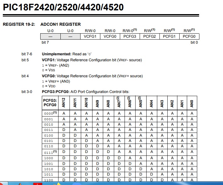
This is from page 225 of the datasheet:

Left justified means that the ADC result is stored in the upper 10 bits of the 16 bit conversion result, with bits 0 to 5 being (presumably, I couldn't find more information about this) zero. Right justified means that the 10 bit result is in bits 0 to 9, and bits 10 to 15 are zero.
This means that depending on the justification you have selected, the conversion result could range from:
\$0\cdots 1111111111000000_2 = 0\cdots 65472\$ (left justified), or
\$0\cdots 0000001111111111_2 = 0\cdots 1023\$ (right justified)
An ADC input \$V_{IN}\$ will produce a conversion result \$N\$ as follows:
\$ N = (V_{IN}-V_{REF-})\frac{65473}{V_{REF+}-V_{REF-}} \$ (left justified), or
\$ N = (V_{IN}-V_{REF-})\frac{1024}{V_{REF+}-V_{REF-}} \$ (right justified)
If you software configure the ADC to use the supplies \$V_{DD}\$ and \$V_{SS}\$ as references, you have \$V_{REF+}=+5V\$ and \$V_{REF-}=0V\$, which corresponds to:
\$ N = V_{IN}\times 13094.6 \$ (left justified), or
\$ N = V_{IN}\times 204.8 \$ (right justified)
The significance of the ±5 count deviation you mentioned (60 to 70) would suggest that you are using right justification, since a change in the least significant bit of a left-justified result (bit 6) would cause the conversion result to change by \$2^6=64\$.
±5 counts out of 1024 is an error of ±0.5%, which is quite bad. Under ideal conditions, this ADC can perform better than ±0.2%. I would hazard a guess at three possible sources of error:
The sensor is powered from a noisy supply, and its output contains some element of supply noise. Without more information about the senor, I can't comment further.
The voltage reference for the ADC is derived from a noisy supply, and will contain noise for the same reason. This can be mitigated by using an external voltage reference, such as the TL431.
There is a layout or signal path impedance problem, causing the ADC input to have noise induced within it from nearby sources of interference. This is a huge topic, too big to cover here. Solve 1 and 2 first, then we can talk about 3.
Lastly, you must never expose any input to voltages lower than \$V_{SS}-0.3V=-0.3V\$, or greater than \$V_{DD}+0.3V=+5.3V\$, and this includes the ADC input. This is described in the "absolute maximum ratings" on page 323. This does not mean that these levels correspond to the conversion range of the ADC; that range is still \$V_{REF-}\$ to \$V_{REF+}\$. To be safe, if your sensor is capable of producing a signal outside of the range 0V to +5V, then you must take measures to protect the ADC input from that.


