0
\$\begingroup\$

In the datasheet it is said that the collector current shall not surpass 20mA. Then there is

VCC = 5 V, RL = 100 Ω, IL = 5 mA

which should be with a voltage drop from collector to emitter of 0.1V -> 4.9V/100Ohm = 0.049mA. Too much.

I believe I don't understand some fundamentals here, so it would be great if someone could help me out.

\$\endgroup\$

1 Answer 1

1
\$\begingroup\$

VCC = 5 V, RL = 100 Ω, IL = 5 mA

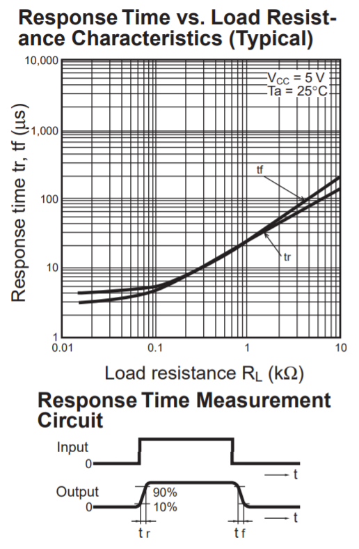
Read what it says; load current is 5 mA. This means that the load voltage is 0.5 volts and not 5 volts. 20 mA is not present in this formula. If you want high speed you sacrifice output voltage level because the load resistance has to be naturally smaller for high-speed: -

enter image description here

\$\endgroup\$
5
  • \$\begingroup\$ I thought the voltage drop across collector-emitter would be constant on saturation. So there is 4.5V across collector-emitter? \$\endgroup\$
    – GRASBOCK
    Commented Sep 29, 2020 at 14:24
  • \$\begingroup\$ @RIJIK Yes, there will be. Opto's are not that great for high speed stuff. Look at the CE saturation spec - it's at a collector current of 0.1 mA and that implies an RL of around 50 kohm and 50 kohm will be poor for speed (in fact it isn't even shown on the graph in my answer). \$\endgroup\$
    – Andy aka
    Commented Sep 29, 2020 at 14:25
  • \$\begingroup\$ I see now. So then it's safe to connect a 100Ohm RL. Just out of curiosity: Why is the rise time larger with a lower collector-emitter voltage? I thought smaller voltages make electronics faster because risetime can be smaller. \$\endgroup\$
    – GRASBOCK
    Commented Sep 29, 2020 at 14:34
  • \$\begingroup\$ Yes, look at the small diagram in the data sheet under the response time graph. I didn't follow what you meant in your 2nd sentence. If you mean why is the rise/fall time greater when the collector saturates more, it's down to the fact that to get a deep saturation requires a higher collector/emitter load resistor and, given that the "base" is tickled only by photons, the capacitance around the base can be problematic with a bigger changing output voltage and a load resistor that is "weaker". \$\endgroup\$
    – Andy aka
    Commented Sep 29, 2020 at 14:43
  • \$\begingroup\$ That explained it very well nevertheless. Thank you kindly \$\endgroup\$
    – GRASBOCK
    Commented Sep 29, 2020 at 20:32

Your Answer

By clicking “Post Your Answer”, you agree to our terms of service and acknowledge you have read our privacy policy.

Not the answer you're looking for? Browse other questions tagged or ask your own question.