3
\$\begingroup\$

I'm trying to design a PCB breakout board for an IC - the MAX86150.

This IC requires three separate power supplies, and it also has three corresponding GND pins. My question is, is there any reason not to simply short the three separate ground pins together and send one common ground for all three power supplies into the breakout board?

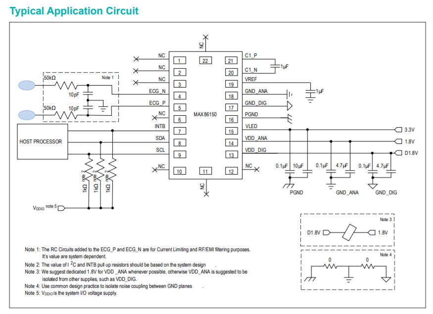
I see that Note 4 indicates they should have zero resistance between them, which I think means they should be shorted to each other, but the circuit diagram does not show them connected by a wire, which makes me worry there's something I don't understand about "common design practices". Are "common design practices" fancier than...connecting them with a trace?

Typical Application Circuit from the datasheet for the MAX86150 IC

\$\endgroup\$
4
  • 1
    \$\begingroup\$ If this is an actual ECG you aren't going to get good performance without a lot of sensitive analog board design experience. It's not just about connections but geometry... If there is a reference design use the actual layout. The very concept of a "breakout board" may be problematic in noise and safety terms. \$\endgroup\$ Commented Oct 9, 2020 at 13:33
  • \$\begingroup\$ Thanks - we're actually not interested in using the ECG functionality, just the optical PPG, so I think we'll be ok. They do have an evaluation kit, I can check and see if they publish the layout for that though, that could be helpful. \$\endgroup\$
    – Brionius
    Commented Oct 9, 2020 at 13:36
  • \$\begingroup\$ Well, the question doesn't have a simple answer. Your best bet is to examine the layouts for the reference design. And you should be thinking in terms of things like planes, not traces. \$\endgroup\$ Commented Oct 9, 2020 at 13:51
  • \$\begingroup\$ is the INTB interrupt line an input or an output pin ? \$\endgroup\$
    – nurabha
    Commented Feb 6, 2021 at 1:46

2 Answers 2

4
\$\begingroup\$

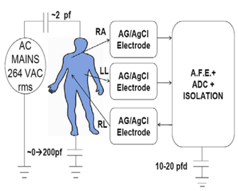
If you need to follow FDA rules (or similar) because this is a product, then there are requirements that should be followed if the design is to be used in a product.

In many designs the MAX86150 is subject to these rules here and IEC 601-1, “Medical Electrical Equipment - Part 1: General Requirements for Safety.
enter image description here
Source: https://www.analog.com/en/technical-articles/mitigation-strategies-for-ecg-design-challenges.html

It might also mean that the MAX86150 could be subject to these rules below:

The designer must examine all scenarios where current between electrodes, or from electrodes to the circuitry or to earth ground, could create single-fault scenarios where the current can exceed 10 µA rms. This source/sink current is a function of frequency, but the 10 µA rms limit ranges in frequency from dc to 1 kHz. From 1 kHz to 100 kHz, the current level linearly increases with frequency: from 10 µA rms at 1 kHz to 1 mA rms at 100 kHz. Above 100 kHz, the current is limited to 1 mA rms.
Source: https://www.analog.com/en/technical-articles/mitigation-strategies-for-ecg-design-challenges.html

Because of these rules many designs might employ separate analog and digital grounding systems, or even isolated ones. In the datasheet it is suggested that isolated digital and analog grounds be used (I don't know how the isolation is to be maintained in the IC)

We suggest dedicated 1.8V for VDD _ANA whenever possible, otherwise VDD_ANA is suggested to be isolated from other supplies, such as VDD_DIG.

So they break out the grounds to give the designer options to satisfy the possible isolation requirements.

If you don't need the isolation (or separate analog and digital grounds) and the design isn't subject to these rules, then the grounds could be tied together.

One problem will be reducing noise and connecting electrodes from a circuit to another body or circuit forms a kind of AC current loop (if you've ever touched an oscilloscope and not grounded yourself you'll find the human body can be a great antenna for 60Hz). A good recommendation on isolation, separate grounds and the like is Electromagnetic Compatibility Engineering.

\$\endgroup\$
0
1
\$\begingroup\$

The issue of separated grounds in ADCs and DACs is a common one. The idea is to avoid 'digital currents' flowing into the analog ground and vice versa thereby corrupting them.

Your specific question is 'should I short these ground pins together ?' Well at some point they do all have to get connected together. Probably best not to do it at the device pins though.

You need to pay similar attention to the analog and digital Vdd too. Don't 'decouple' Vdd_dig into GND_ana for example !

As it's a breakout board, there will inevitably be some compromise involved in ensuring the integrity of the grounds. This is a design decision.

\$\endgroup\$

Your Answer

By clicking “Post Your Answer”, you agree to our terms of service and acknowledge you have read our privacy policy.

Not the answer you're looking for? Browse other questions tagged or ask your own question.