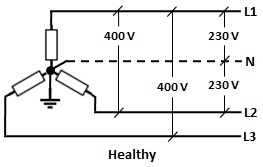
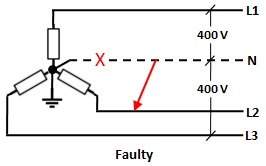
What issues can cause the output voltage of a transformer to suddenly increase from 230 volts to 400 volts (in the case of any transformer and in the case of the delta to Y configuration of the transformer)? What would be the voltage between a phase and ground if a coil of the Y side (secondary) gets short because of heating or any other reason?
\$\begingroup\$
\$\endgroup\$
8
-
\$\begingroup\$ Do you have any context to this? Like, how does that question arise? There's quite a few things, but I'd guess you'd want to rule out "cat overlords playing on substation operator table"... \$\endgroup\$– Marcus MüllerCommented Oct 24, 2020 at 21:23
-
\$\begingroup\$ In my town, a few days back, the surge of voltage (failure of the transformer) caused many houses to lose useful appliances. The electric poles in my county going to the transformers mostly contain 3 wires (I think 3 phase current), but each house is provided with a phase and neutral wire. Hence, I believe that the transformers might be delta (primary) to Y (secondary). \$\endgroup\$– ZZ1Commented Oct 24, 2020 at 21:42
-
\$\begingroup\$ hm, how do you know it's a failure of the transformer? the fact that many households were affected might indicated that it was a surge on the common higher-voltage line. \$\endgroup\$– Marcus MüllerCommented Oct 24, 2020 at 21:44
-
\$\begingroup\$ All the affected households were being served by the same transformer. It might not be because of the transformer but that's what I thought. Could you suggest some keywords that I could search, that might help me enhance my understanding? \$\endgroup\$– ZZ1Commented Oct 24, 2020 at 21:49
-
1\$\begingroup\$ @MarcusMüller I'm pretty sure it was the cat overlords. \$\endgroup\$– John DCommented Oct 25, 2020 at 0:14
|
Show 3 more comments
1 Answer
6
-
1\$\begingroup\$ I'm quite certain this is the answer OP is looking for, but I'm also quite certain you must remove the ground symbol in the second figure (or both). Pictute a phasor diagram: In a grounded system, you will move L2 to 0V, while keeping unchanged. Thus L1-N = 230V still. If, however, it's isolated, then you will "move ground" over to L2, and have L1-N = L1-L2 = 400 V. +1 though. :) \$\endgroup\$– CG.Commented Dec 2, 2020 at 10:57
-
\$\begingroup\$ @CG, The schematic pertains to a TT System in which the neutral is earthed at the transformer and nowhere else. When the neutral wire breaks, it will no longer be connected to earth and the short thereupon with L2 will result in its functioning as L2 itself. \$\endgroup\$– vu2nanCommented Dec 2, 2020 at 19:00
-
\$\begingroup\$ Ok. I thought the ground symbol in the transformer was physical connection to ground, not just a way to indicate 0V (or reference voltage). I'm used to HV systems, and in these systems a ground symbol means there is a connection to ground at that point (e.g. a ground rod, a connection to a grounding mesh in a substation or the like). \$\endgroup\$– CG.Commented Dec 3, 2020 at 7:25
-
\$\begingroup\$ @CG, The neutral point is physically connected to ground! \$\endgroup\$– vu2nanCommented Dec 3, 2020 at 9:50
-
\$\begingroup\$ In that case, wouldn't the voltage of L2 be
L2=N=0, thus the only place you have 400 V is between L1-L3? \$\endgroup\$– CG.Commented Dec 3, 2020 at 11:26


