The key to understanding how the electric field follows Ohm's law in a good but non-perfect conductor, is: surface charges.
When the conductor is connected to the supply, it is initially subject to the electric field generated by the supply's electrodes. Being a good conductor, the (nearly) free charges inside will react to that field by quickly rearranging themselves on the surface of the conductor (very much like they do in the electrostatic case in order to make the field inside zero.)
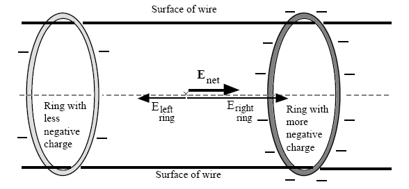
With cylindrical metallic conductors, you can think of rings of charge, whose density will vary from point to point according to the geometry of the wire. For example, on a straight piece of wire, far away from other sources, two uniformly charged rings of different density will produce and axial field directed form the more positive (least negative) ring to the more negative (least positive) ring, like this:

Source: Chabal and Sherwood's paper cited below
By suitably changing the charge density of these rings along the conductor, the electric field inside can be made to follow the bends of the circuit. Both positive and negative charge gradients work:

Source: "Understanding Electricity and Circuits: What the Text Books Don’t Tell You", Ian M. Sefton
The actual distribution of charges is in general more complicated and the charge density does not even need to be uniform on the same ring, but the principle is that the total internal electric field, superposition of the original field generated by the supply and the field generated by the surface charge, will be directed along the conductor and will have magnitude \$E = j / \sigma\$, where \$j\$ is the current density and \$\sigma\$ is the conductivity of the material the wire is made of.

Source: Chabal and Sherwood's paper cited below
So, to answer your question, the field is constant in magnitude and is directed along the direction of the conductor.
How does the electric field behaves on the surface of the conductor?
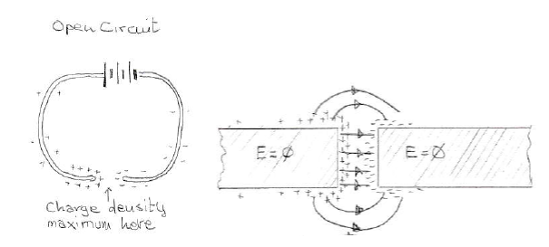
In the electrostatic case, where current does not flow, the charge is distributed on the surface of the conductor in such a manner as to completely neutralize the electric field inside. In this case \$E = 0\$ inside but it is generally non-zero on the surface. Due to the continuity of the tangential component of the electric field at the interface between different materials, the electric field in the electrostatic case can only be perpendicular to the surface.
We can see this field configuration when the wire is not completing a circuit and no current is flowing:

With the circuit open we are in an electrostatic context: the field inside the conductor is zero, while on the surface it is perpendicular to the surface
When we close the (battery supplied) circuit on a conductor of finite conductivity, the charges on the surface will redistribute themselves very rapidly (with relaxation times) resulting in the establishment of a constant electric field directed along the wire, so that a steady current will flow. The surface charge density will therefore change radically; in particular, in the case of a single resistive wire, there will also be a point along the circuit where the density becomes zero:

Variation in surface charge density distribution when the circuit is closed
In this newly established quasi-static condition the field inside the conductor is no longer exactly zero but has the (usually tiny) value \$E = j / \sigma\$ that satisfies the local form of Ohm's law. Since the tangential component of the electric field has to be conserved at the interface between materials, the field on the surface will no longer be exactly perpendicular to it but will change from nearly perpendicular and slightly slanted toward the direction of the current (where charge density is highest) to nearly completely tangential (in the points where charge density drops near-zero levels.)

(Sources: top - Andre Koch Torres Assis, Julio Akashi Hernandes, "The Electric Force of a Current", bottom - "Understanding Electricity and Circuits: What the Text Books Don’t Tell You", Ian M. Sefton)
When the circuit is close, the field inside acquires a tangential component that follows the wire, making the field at the interface slanted in the direction of positive current.
In general there are different configurations the electric field can assume, according to the actual distribution of charge around the conductor at a given point. In two dimensions, you can encounter the following situations (highlighted by the yellow disks in Muller's simulation shown in the references.)

While the electric field inside the current-carrying conductor is constant and directed along the wire, immediately outside it can assume different configuration according to the local and nearby distribution of charges
It all depends on the distribution of surface charge, either locally (for example charges tend to accumulate at sharp bends in order to steer the field inside the conductor there) or from nearby parts of the circuit (as shown in Muller's simulation below).
How does the internal field changes from \$E=0\$ to \$E = j / \sigma\$?
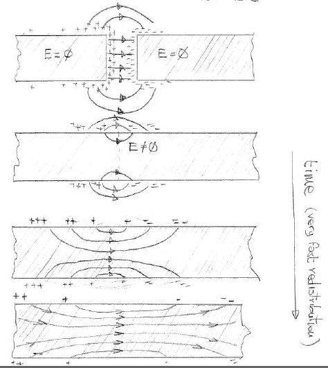
You might wonder how the conductor evolves from the condition E = 0 to the condition \$E = j / \sigma\$, so here is a very rough 'still animation' showing a piece of straight conductor located that is not subject to other charges distributions apart from the ring of charges along its length (meaning it's reasonably far from the battery and other sharp bends in the circuits, where surface charge accumulates):

When we close the circuit, the surface charge on the opposite extremities of the wire recombine and redistribute itself, progressively creating electric field lines inside the conductor that gets straightened out until the field is directed along the conductor
This is just a free-hand sketch, since I do not have links to actual simulations at hand.
References
- For a qualitative discussion, see Chabay and Sherwood, both their book "Matter and Interactions" and their paper "A unified treatment of electrostatics and circuits" published on the American Journal of Physics.
- Another didactic article is that written by Ian M. Sefton for the Science and Teachers Workshop 2002: "Understanding Electricity and Circuits: What the Text Books Don’t Tell You". This article also shows the correct direction of the Poynting vector (and should be read by certain youtubers.)
- There is a book that treats this topic in detail: Andre Koch Torres Assis and Julio Akashi Hernandes, "The Electric Force of a Current: Weber and the Surface Charges of Resistive Conductors Carrying Steady Currents", 2007. Freely available on ResearchGate at this link.
- For an example simulation see Rainer Muller, "A semiquantitative treatment of surface charges in DC circuits", published on the same journal (Am. J. Phys. 80 (9), September 2012)

Simulation in Rainer Muller's paper (yellow disks added by me): charge density in blue-red, note the field directed along the conductor inside the wires and the accumulation of charge at the discontinuities in resistivity and at the bends in the wire. Also note the slanted field immediately outside the straightest portions of the wire. Since the rings of charge can have non-uniform density, sometimes the field emerges from the surface, sometimes it impinges into it.
- For a theoretical example, there is a nice exercise on Sommerfeld's Lectures on Theoretical Physics (volume 3: Electrodynamics, p. 125, "Detailed treatment of the field of a straight wire and a coil".)
- It would be unfair not to mention the 1962 paper where Jefimenko performed experiments with high voltage sources and grass seeds in mineral oil to show the electric field lines around conductors: "Demonstration of the Electric Fields of Current-Carrying Conductors", American Journal of Physics 30, 19
(Also, in my answer here, towards the end, I show how to wrangle Maxwell's equations to explain how charge density, for a given current density, changes according to gradients in conductivity and permeability. This explains why charge accumulate at the surface of the wire and at interfaces with material of different resistivity)


