I have 1 question relative to the LR tunnel diode oscillator. If we increase the inductance of the inductor frequency is reduced but shouldn't the output voltage be increased as well? I am running simulations on falstad but cannot detect any changes, has anyone else encountered this issue before me?
-
1\$\begingroup\$ There is no generic LR tunnel diode oscillator hence, you should post a circuit. \$\endgroup\$– Andy akaCommented Nov 27, 2020 at 16:10
-
\$\begingroup\$ Why do you think that the output amplitude should increase? Wouldn't the output amplitude be limited by the width of the negative resistance region of the diode ? \$\endgroup\$– AJNCommented Nov 27, 2020 at 17:13
-
\$\begingroup\$ AJN OK but if we have a big inductor and the jump is greater than the width of the negative resistance shouldn't we have more voltage? \$\endgroup\$– The Force AwakensCommented Nov 27, 2020 at 17:23
-
2\$\begingroup\$ @TheForceAwakens: It usually helps if you post the circuit you are working with. It doesn't hurt you to provide a drawing, and it clears up uncertainties. It is easier for everyone if there is a single drawing to refer to rather than everyone imagining their own different version. \$\endgroup\$– JRECommented Nov 27, 2020 at 17:42
1 Answer
Your oscillator is a relaxation oscillator. L and R affect the timing - how fast the current grows. The voltage amplitude is determined by the knee points in the I vs V curve of the tunnel diode.
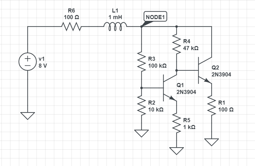
Unfortunately I haven't a tunnel diode model for easy simulation. But i borrowed a transistor circuit from my old answer for another question. It has voltage stable dynamic negative resistance of the same type:
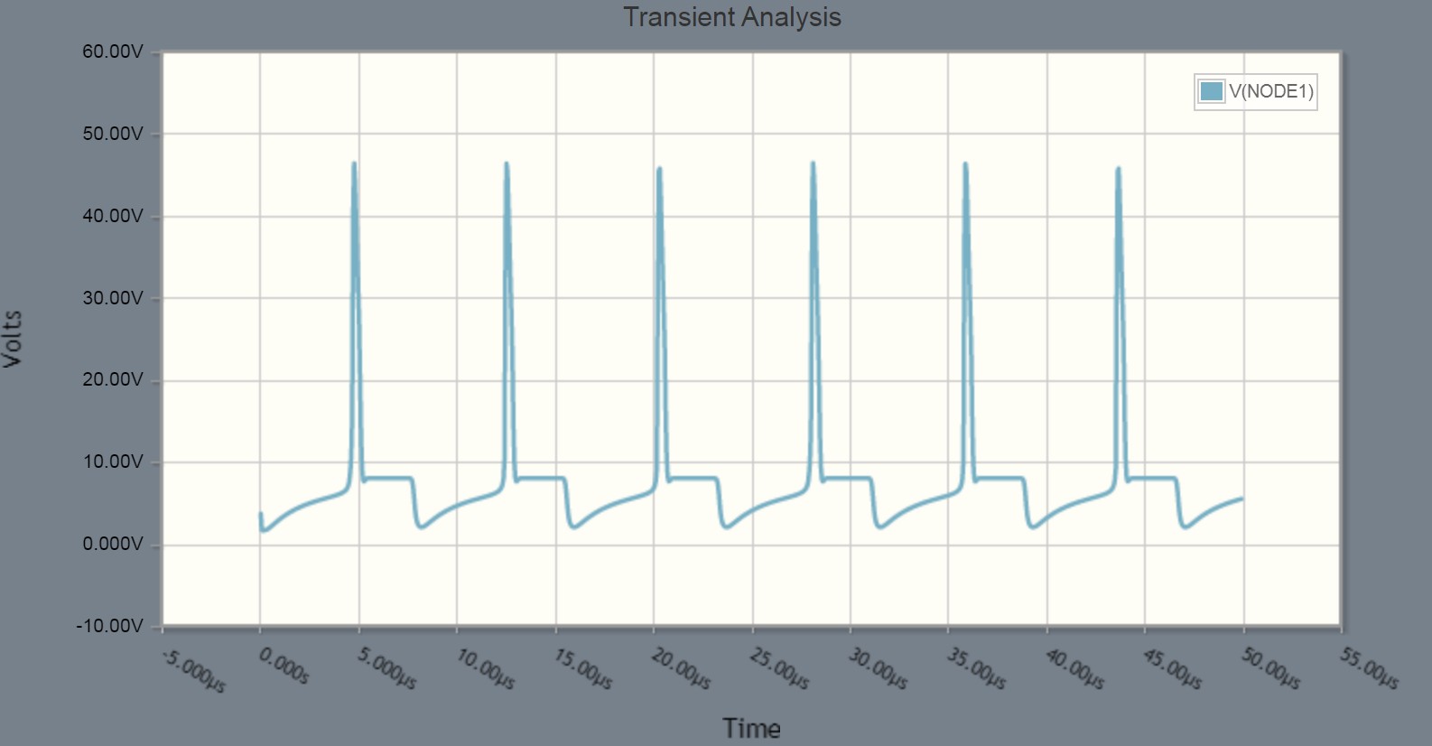
When the circuit starts the current in the inductor grows gradually. Also the voltage of NODE1 grows. Soon it reaches the value where the negative resistance starts. The transistor circuit starts to take less current. The voltage of the inductor jumps to keep the current. going, but the energy of the magnetic field is soon dissipated and the current ceases. Voltage V1=8 volts is less than the next possible positive resistance voltage above the negative resistance region, so the operating point drops to lower voltage than the negative resistance area and a new oscillation cycle starts.
The max voltage peak is as high as needed to allow the the inductor current to continue. My transistor circuit seemingly passes enough current when the voltage is 47V. If I had bigger inductance the peak would be wider and the time interval between peaks would be longer, but the peak wouldn't be higher.
You probably do not see that tens of volts peak if you have a tunnel diode. The negative resistance occurs at forward voltages well below 1 volt, at 1V or more it's like a normal diode.
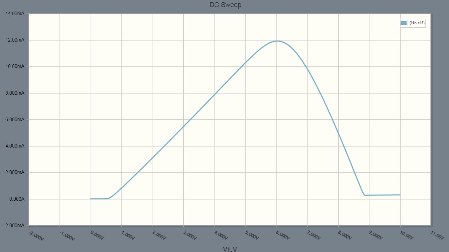
The transistor circuit without L1 and R6 has this I vs V curve:
The old question is this: What is the physical meaning of negative resistance?


