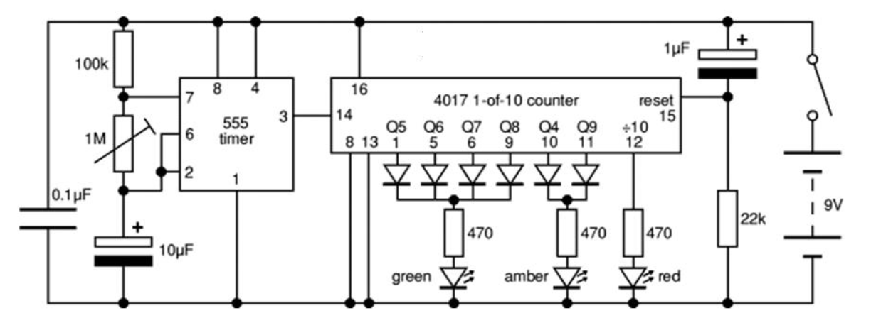
It is called a decoupling capacitor.
Real wires and traces aren't perfect lines on a page that perfectly connect two components together. They have inductance which produces voltage drops and voltage spikes when the component's current demand changes due to wire inductance between the component and the battery. So you can stick an inductor in the middle of every wire/trace line on that schematic.
The capacitor is placed as close to the component as possible with minimal trace length and (something not shown on a schematic) and acts as a local power supply to get around this.
It's the kind of thing where if the circuit is undemanding and tightly built, you may get away without it. But demanding or messily build circuits won't work at all without it and even if the circuit runs without it, it will run better and quieter with it.
If it is required but missing, the circuit may outright not work at all, work some of the time but not all of the time, or exhibit very strange behaviours. There's almost no point to debugging a circuit without decoupling capacitors until decoupling capacitors are added.

