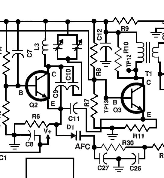
 I have a question about how the varactor on the transistor's emitter can change the frequency of the modified Colpitts oscillator on the collector of this circuit. The junction of the varactor and R30 has 3.4VDC on it at 10.7MHz (FM IF). This voltage comes from the ratio detector. When the frequency increases above 10.7MHz, the ratio detectors output drops and the voltage at the cathode of the varactor drops. Conversely, when the frequency drops, the voltage increases. Both voltage swings were about +/- 10mV so small in either direction. So exactly how does a varying capacitance on the emitter change the frequency of an oscillator on the collector.
\$\begingroup\$
\$\endgroup\$
3
-
4\$\begingroup\$ And the price for the most crowdedly drawn schematic goes to.... I'm mentally redrawing parts of this schematic just to get an idea of how it would look weren't pixels so darn expensive! This is really unnecessarily hard to understand. This is no critique of your question, just a note that things might generally be easier to understand for you if the authors of schematics try less hard to cram as many schematic symbols as possible into small space. \$\endgroup\$– mmmmCommented Mar 16, 2021 at 3:33
-
4\$\begingroup\$ That is an abysmally drawn schematic! \$\endgroup\$– HearthCommented Mar 16, 2021 at 4:21
-
\$\begingroup\$ Because C27 and C12 are both grounded. Thus C9/D1/C27 are in parallel with the tuned circuit, allowing D1 to affect its resonant frequency. \$\endgroup\$– user16324Commented Mar 16, 2021 at 12:16
Add a comment
|
